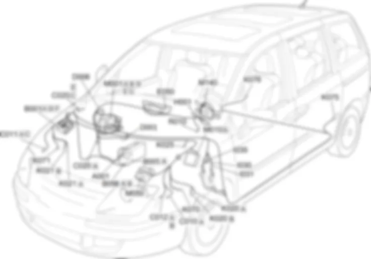
Components - ABS - Fiat ULYSSE 2.2 16V JTD fino a 04/03
| Component code | Description | Reference to the assembly |
| A001 | BATTERY | - |
| B001 | ENGINE COMPARTMENT JUNCTION UNIT | |
| B005 | MAXI FUSE BOX | - |
| B098 | ADDITIONAL FUSE BOX | - |
| C010 | LEFT FRONT EARTH | - |
| C011 | RIGHT FRONT EARTH | - |
| C012 | ABS FRONT EARTH | - |
| C020 | PASSENGER SIDE DASHBOARD EARTH | - |
| D001 | FRONT/DASHBOARD COUPLING | - |
| D006 | FRONT/REAR COUPLING | - |
| E050 | INSTRUMENT PANEL | |
| H001 | Ignition switch | |
| I030 | BRAKE PEDAL SWITCH | |
| I031 | CLUTCH PEDAL SWITCH | - |
| I035 | Safety switch on brake pedal for cruise control | - |
| K020 | LEFT BRAKE PAD WEAR SENSOR (SWITCH) | |
| K021 | RIGHT BRAKE PAD WEAR SENSOR (SWITCH) | |
| K025 | BRAKE FLUID LEVEL SENSOR (SWITCH) | - |
| K070 | LEFT FRONT WHEEL SENSOR FOR ABS | |
| K071 | RIGHT FRONT WHEEL SENSOR FOR ABS | |
| K075 | LEFT REAR WHEEL SENSOR FOR ABS | |
| K076 | RIGHT REAR WHEEL SENSOR FOR ABS | |
| M001 | BODY COMPUTER | |
| M010 | ENGINE MANAGEMENT CONTROL UNIT | |
| M050 | ABS CONTROL UNIT | |
| M140 | WARNING LIGHTS AND MILOMETER CONTROL UNIT (NSO) | - |
| R010 | MULTIPLE DIAGNOSTIC COUPLING | - |
The vehicle is fitted with an ABS braking system which prevents the wheels from locking during braking, makes the best possible use of the grip conditions available and keeps the vehicle as easy as possible to control during emergency braking.The ABS is an additional part of the basic braking system; it is disabled if there is a problem, with the braking system working the same way as for a vehicle without ABS.The advantage of ABS over conventional systems is that it makes it possible to maintain maximum manoeuvrability even when braking hard in poor grip conditions, preventing the wheels from locking.The system is completed by the EBD system (Electronic Brake Distributor) which distributes the brake force by means of the ABS sensors and control unit.The "ABS failure" warning light and the "minimum brake fluid level" warning light coming on simultaneously with the engine running means that there is a problem with the EBD system; in this case, the wheels could lock during sharp braking.The "ABS failure" warning light coming on by itself with the engine running usually means that there is a problem with the ABS only.In this case, the braking system will work properly, just without the anti-lock function.The operation of the EBD system may also be affected under these circumstances.If the "minimum brake fluid level" warning light only comes on, this means that the hydraulic system fluid level is too low.On this version, the system is only available in the basic configuration.If the vehicle in question is equipped with the ESP function and the additional TC/ASR, MBA/HBA and MSR functions,The basic ABS system components are:
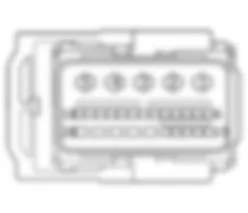
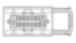
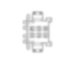
The ABS function is managed by ABS control unit M050.Control unit M050 is supplied at connector A from engine compartment control unit B001:- at pin 2, by a line protected by fuse MF02 from pin 2 of connector D;- at pin 3, by a line protected by fuse MF03 from pin 3 of connector D;- at pin 18, by a line protected by fuse F07 from pin 3 of connector F;Control unit M050 communicates via the CAN line (pin 26 and 15, 14 and 25 connector A) with the body computer node M001) (pins 2 and 4, 25 and 27 connector E, pins 8 and 10 connector D), with engine control unit M010 (pins A3 and A4 connector A), with instrument panel E050 (pins 6 and 12), with warning light and odometer control unit M140 (pins 2 and 5) and with engine compartment control unti B001 (pins 11 and 12 connector F).Control unit M050 (pins 16-5, 9-10, 6-17, 8-19 connector A respectively) controls the speed of each wheel via left front wheel sensor K070 (pin 1 and 2), right front wheel sensor K071 (pins 1 and 2), left rear wheel sensor K075 (pins 1 and 2) and right rear wheel sensor K076 (pins 1 and 2).Left brake wear sensor K020 and right brake wear sensor K021 (pin 1 connector A) send an earth signal to control unit M050 (pin 22 connector A).Brake fluid level signal sensor K02 (pin 1) is connected to M050 (pin 21 connector A), which sends signals (via the CAN line) to control units E050 and M140.Instrument panel E050 (pin 13) and warning light and odometer control unit M140 (pin 4) are supplied by body computer node M001 (pin 6 connector D) via a line protected by fuse F14.767


