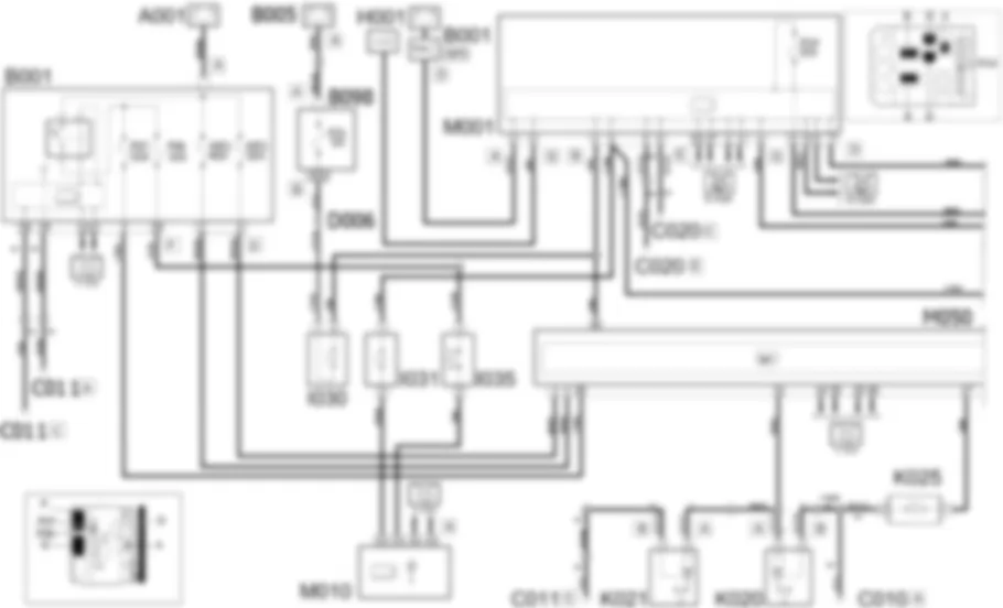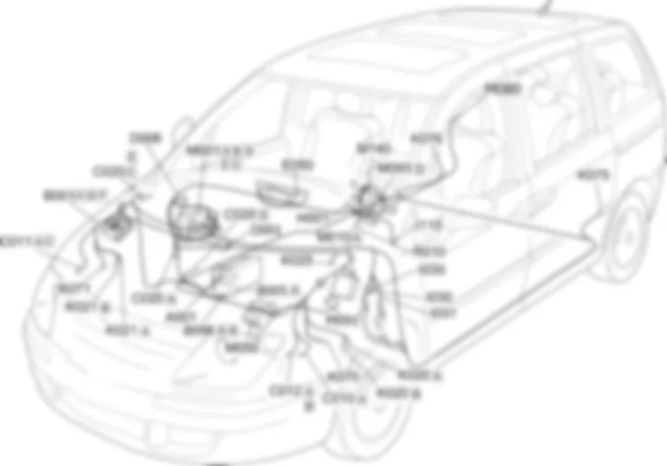
Components - ESP - Fiat ULYSSE 2.2 16V JTD fino a 04/03
| Component code | Description | Reference to the assembly |
| A001 | BATTERY | - |
| B001 | ENGINE COMPARTMENT JUNCTION UNIT | |
| B005 | MAXI FUSE BOX | - |
| B098 | ADDITIONAL FUSE BOX | - |
| C010 | LEFT FRONT EARTH | - |
| C011 | RIGHT FRONT EARTH | - |
| C012 | ABS FRONT EARTH | - |
| C020 | PASSENGER SIDE DASHBOARD EARTH | - |
| D001 | FRONT/DASHBOARD COUPLING | - |
| D006 | FRONT/REAR COUPLING | - |
| E050 | INSTRUMENT PANEL | |
| H001 | Ignition switch | |
| I030 | BRAKE PEDAL SWITCH | |
| I031 | CLUTCH PEDAL SWITCH | - |
| I035 | Safety switch on brake pedal for cruise control | - |
| I115 | STABILITY CONTROL SYSTEM SWITCH | - |
| K020 | LEFT BRAKE PAD WEAR SENSOR (SWITCH) | |
| K021 | RIGHT BRAKE PAD WEAR SENSOR (SWITCH) | |
| K025 | BRAKE FLUID LEVEL SENSOR (SWITCH) | - |
| K070 | LEFT FRONT WHEEL SENSOR FOR ABS | |
| K071 | RIGHT FRONT WHEEL SENSOR FOR ABS | |
| K075 | LEFT REAR WHEEL SENSOR FOR ABS | |
| K076 | RIGHT REAR WHEEL SENSOR FOR ABS | |
| M001 | BODY COMPUTER | |
| M010 | ENGINE MANAGEMENT CONTROL UNIT | |
| M050 | ABS CONTROL UNIT | |
| M80 | CENTRAL DOOR LOCKING CONTROL UNIT | - |
| M091 | SLEWING CONTROL UNIT | - |
| M093 | STEERING WHEEL NODE CONTROL UNIT (NVO) | |
| M140 | WARNING LIGHTS AND MILOMETER CONTROL UNIT (NSO) | - |
| R010 | MULTIPLE DIAGNOSTIC COUPLING | - |
The vehicle is fitted with an ABS braking system which prevents the wheels from locking during braking, makes the best possible use of the grip conditions available and keeps the vehicle as easy as possible to control during emergency braking.The ABS is an additional part of the basic braking system; it is disabled if there is a problem, with the braking system working the same way as for a vehicle without ABS.The advantage of ABS over conventional systems is that it makes it possible to maintain maximum manoeuvrability even when braking hard in poor grip conditions, preventing the wheels from locking.The system is completed by the EBD system (Electronic Brake Distributor) which distributes the brake force by means of the ABS sensors and control unit.The "ABS failure" warning light and the "minimum brake fluid level" warning light coming on simultaneously with the engine running means that there is a problem with the EBD system; in this case, the wheels could lock during sharp braking.The "ABS failure" warning light coming on by itself with the engine running usually means that there is a problem with the ABS only.In this case, the braking system will work properly, just without the anti-lock function.The operation of the EBD system may also be affected under these circumstances.If the "minimum brake fluid level" warning light only comes on, this means that the hydraulic system fluid level is too low.On this version, the system also includes the ESP function.ESP (Electronic Stability Program) is an electronic system that controls the stability of the vehicle, intervening on the engine torque and introducing differentiated braking for the wheels in the case of a loss of grip restoring the vehicle to the correct path.Whilst driving the vehicle is subject to lateral and longitudinal forces which can be controlled by the driver as long as the tyres hold the road sufficiently well; when this is no longer the case, the vehicle starts to drift from the desired path. Especially when driving on uneve road surfaces (such as cobblestones or where there is water, ice or soil), changes in speed (during acceleration or braking) and/or trajectory (bends or the need to avoid obstacles) can cause a loss in grip for the tyres.When the sensors detect conditions that could lead to the vehicle slipping, the ESP system intervenes on the engine and the brakes producing a stabilizing torque.The ESP system switches on automatically each time the engine is started up; it can be switched off and switched back on again manually by pressing the button on the left side of the dashboard.The basic ESP system components are:
The ESP function is managed by ABS/ESP control unit M050.Control unit M050 is supplied at connector A from engine compartment control unit B001:- at pin 2, by a line protected by fuse MF2 from pin 2 of connector D;- at pin 28, by a line protected by fuse F07 from pin 3 of connector F;Control unit M050 communicates via the CAN line (pins 25 and 45, 14 and 25 connector A) with the body computer node M001) (pins 2 and 4, 25 and 27 connector E, pins 8 and 10 connector D), with engine control unit M010 (pins A3 and A4 connector A), with steering wheel node control unit M093 (pins 1 and 2), with yaw control unit M091 (pins 2 and 3), with instrument panel E050 (pins 6 and 12), with warning light and odometer control unit M140 (pins 2 and 5) and with engine compartment control unit B001 (pins 11 and 12 connector F).Control unit M050 (pins 26-5, 9-10, 6-27, 8-29 connector A respectively) controls the speed of each wheel via left front wheel sensor K070 (pin 1 and 2), right front wheel sensor K071 (pins 1 and 2), left rear wheel sensor K075 (pins 1 and 2) and right rear wheel sensor K076 (pins 1 and 2).Pin 33 of connector A of control unit M050 is connected to pin 14 of door lock control unit M080.The yaw sensor is built into control unit M050, which activates the stability control system when a vehicle stability situation is detected (understeer or oversteer).Left brake wear sensor K020 and right brake wear sensor K021 (pin 1 connector A) send an earth signal to control unit M050 (pin 31 connector A).Brake fluid level signal sensor K02 (pin 1) is connected to M050 (pin 17 connector A), which sends signals (via the CAN line) to control units E050 and M140.Instrument panel E050 (pin 13) and warning light and odometer control unit M140 (pin 4) are supplied by body computer node M001 (pin 6 connector D) via a line protected by fuse F14.The ESP system may be cut out by pressing switch I115:- the power (pin 4) is supplied by body computer node M001 (pin 7 connector D).- the cut-out signal (pin ) reaches instrument panel E050 (pin 4).767

