Wiring Diagram - AUTOMATIC TRANSMISSION - Fiat ULYSSE 2.2 16V JTD fino a 04/03
Components - AUTOMATIC TRANSMISSION - Fiat ULYSSE 2.2 16V JTD fino a 04/03
| Component code | Description | Reference to the assembly |
| Engine compartment junction unit | 5505A |
| Left front earth | - |
| Right front earth | - |
| Passenger dashboard earth | - |
| Front/dashboard coupling | - |
| Dashboard/rear coupling | - |
| Instrument panel | 5560B |
| Ignition switch | 5520A |
| Brake pedal switch | 5550D |
| Body computer | 5505A |
| Warning lights and milometer control unit (NSO) | - |
| See descriptions R010 MULTIPLE DIAGNOSTIC COUPLING | Multiple diagnostic coupling | - |
Location Components - AUTOMATIC TRANSMISSION - Fiat ULYSSE 2.2 16V JTD fino a 04/03
Components - AUTOMATIC TRANSMISSION - Fiat ULYSSE 2.2 16V JTD fino a 04/03
| Component code | Description | Reference to the assembly |
| B001 | Engine compartment junction unit | 5505A |
| C010 | Left front earth | - |
| C011 | Right front earth | - |
| C020 | Passenger dashboard earth | - |
| D001 | Front/dashboard coupling | - |
| D020 | Dashboard/rear coupling | - |
| E050 | Instrument panel | 5560B |
| H001 | Ignition switch | 5520A |
| I030 | Brake pedal switch | 5550D |
| M001 | Body computer | 5505A |
| M140 | Warning lights and milometer control unit (NSO) | - |
| R010 | Multiple diagnostic coupling | - |
Operational Description - AUTOMATIC TRANSMISSION - Fiat ULYSSE 2.2 16V JTD fino a 04/03
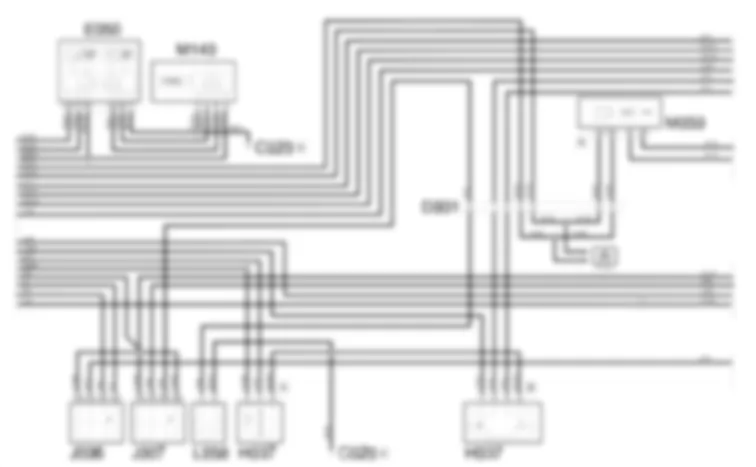
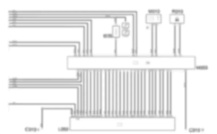
Automatic transmission control unit M055 controls and regulates the entire electronic gearbox management system (CAE).A direct battery power suppy is supplied by body computer node M001 (pin 11 connector B) from a line protected by fuse F23, located inside the control unit, at pin 56 of control unit M055.An ignition-operated power supply is supplied by engine bay control unit B001 (pin 4 connector C) from a line protected by fuse F04, located inside the control unit, at pin 27 of control unit M055.Pin 28 of M055 is earthed.The information is sent, via the CAN, from control unit M055 (from pins 29, 30) to the engine management control units involved M010 and ABS/ESP M050.Relays J006 (pin 1A) and J007 (1B, 3B) receive an ignition-controlled supply from the line protected by fuse F04, located in junction unit B001.The other end of the coil for J006 is connected to the solenoid valve unit L050 at pin A5.When the ignition switch is turned to osition M, the supply reaches pin 3A of relay J006 from pin 3 connector A of H001.The solenoid valve unit L050 only allows starting in certain conditions (e.g. if the brake pedal is pressed).A negative signal from the solenoid valve unit L050 energizes the coil for relay J006: in this way a supply arrives from the line for pin A5 of J006 energizing the starter motor A020The starting command is only supplied when the control unit M055 receives the "brake pedal pressed" signal at pin 43 coming from switch I030 and when there is no "brake pedal released" signal at pin 16 coming from switch I035.The brake pedal pressed signal comes from the brake pedal switch I030, connected to the body computer node M001 at pin 2 of connector B and is supplied directly by the ignition switch H001.Switch I035 receives a supply from the ignition-controlled line protected by fuse F18 of the body computer M001.767there is a second "redundant" switch on the brake pedal: the "basic" switch (I030) is the "normally open" type (when the pedal is pressed, the switch closes), whilst the "redundant" switch (I035) is the "normally closed" type (when the pedal is pressed, the switch contact opens): the system checks the consistency of the "pedal pressed" information in this way.Relay J007 supplies the automatic transmission lever lock solenoid L058 when electronic control unit M055 excites the relay coil via a negative signal from pin 11.The internal contact of the relay closes and the ignition-operated power supply received at pin 3B is sent on to electromagnet L058 from pin 5B.The KEY LOCK signal (engine immobilizing if the gearbox is not in P or N) is sent by control unit M055, from pin 3 to the body computer node M001, pin 36 of connector M.The solenoid valve unit L050 receives an ignition-controlled supply at pin A1 of the engine compartment junction unit B001 (pin 10 connector C) from the line protected by fuse F04, located in the junction unit; pin A4 is earthed.The reverse gear engaged signal is sent from pin A2 to the body computer node M001 (pin 5 connector B) which controls the switching on of the reversing lightsAll the other pins are connected to the automatic transmission control unit M055; control unit M055 communicates directly through numerous signals with the solenoid valve unit L050 which contains the control valves, pressure regulators and some sensors.The management of the gearbox can be fully automatic (i.e. managed completely by control unit M055) or semi-automatic, in other words setting the gears through the gear lever, switch unit H037 connector B; the latter receives a supply from the body computer node M001 (pin 6 connector F) from the line protected by fuse F18 located in the junction unit. The control unit is informed, from unit H037 connector B, of the automatic or manual management, at pins 36 and 37 of M055.The engagement of the "snow" function by pressing the special button in unit H037 connector A, is communicated to the body computer M001, at pin 16 connector L and from there to the control unit M055, via the CAN.The LED to show that the function is on is supplied by the line protected by fuse F12 located in the body computer.Control unit M055 sends the required information, via the CAN, to instrument panel E050 and odometer warning light node M140 for the management of the warning lights and the gears engaged display.The control unit autodiagnostic data can be read by connecting to the diagnostic socket.The automatic transmission control unit M055 is connected, via the K line, from pin 18 to the diagnostic socket R010, pin 7; it is also connected through diagnostic line L, from pin 17 of M055 to pin 15 of R010Description - AUTOMATIC TRANSMISSION - Fiat ULYSSE 2.2 16V JTD fino a 04/03
A loss in tyre inflation pressure can result in serious problems:Burst tyreA considerable deterioration in the vehicle''s road holding and braking stability.Irregular, rapid wear of the tyres.Increased fuel consumption.
The insufficient pressure notification system is designed to satisfy this need to constantly check the four wheels of the vehicle.The information is displayed both via the NSO (milomter warning lights node) by the STOP warning light coming on and via the multifunction screen node in the form of a message in the display.The system consists of:four pressure sensors inside the wheels transmitting a code via radiofrequency (R.F.) and allowing the pressure to be measuredone R.F. signal reception and management control unit located inside the steering column switch unit
The reception control unit also analyzes the correct operation of each sensor following no response from the sensor (malfunction or batteries run down) or if new sensors are being programmed.The sensors are designed to prevent possible false alarms caused by differences in pressure due to climatic and environmental conditions during the normal use of the vehicle.767the wheel control system does not check the spare wheel, does not deal with over inflation and does not allow which wheel(s) has(have) the problem to be precisely identified.
| Component code | Description | Reference to the assembly |
| B001 | Engine compartment junction unit | 5505A |
| C010 | Left front earth | - |
| C011 | Right front earth | - |
| C020 | Passenger dashboard earth | - |
| D001 | Front/dashboard coupling | - |
| D020 | Dashboard/rear coupling | - |
| E050 | Instrument panel | 5560B |
| H001 | Ignition switch | 5520A |
| I030 | Brake pedal switch | 5550D |
| M001 | Body computer | 5505A |
| M140 | Warning lights and milometer control unit (NSO) | - |
| R010 | Multiple diagnostic coupling | - |
ENGINE COMPARTMENT JUNCTION UNIT
B001A
B001A
B001A
B001B
B001B
B001B
B001B
B001B
B001B
B001B
B001C
B001C
B001C
B001C
B001C
B001C
B001C
B001D
B001D
B001D
B001E
B001E
B001F
B001F
B001F
B001F
B001G
B001G
B001G
B001G
B001G
B001G
B001G
LEFT FRONT EARTH
C010A
C010A
C010A
C010B
C010B
C010B
C010B
C010C
C010C
RIGHT FRONT EARTH
C011A
C011A
C011B
C011B
C011B
C011C
C011C
C011C
PASSENGER SIDE DASHBOARD EARTH
C020A
C020A
C020B
C020B
C020C
C020C
C020D
C020D
C020E
C020E
C020F
C020F
FRONT/DASHBOARD COUPLING
D001
D001
D001
D001
D001
D001
D001
DASHBOARD/REAR COUPLING
D020A
D020A
D020A
D020A
D020A
D020A
D020B
D020B
D020B
D020B
D020C
D020C
D020C
D020C
D020C
D020C
INSTRUMENT PANEL
E050
E050
E050
E050
Ignition switch
H001
H001A
H001A
H001A
H001A
H001B
BRAKE PEDAL SWITCH
I030
I030
BODY COMPUTER
M001A
M001A
M001B
M001B
M001B
M001B
M001B
M001C
M001C
M001D
M001D
M001D
M001D
M001E
M001E
M001E
M001F
M001F
M001F
M001F
M001G
M001G
M001H
M001H
M001I
M001I
M001L
M001L
M001L
M001L
M001M
M001M
M001M
M001M
M001M
WARNING LIGHTS AND MILOMETER CONTROL UNIT (NSO)
M140
M140
M140
M140


