Components - DIAGNOSTIC MULTIPLE CONNECTOR - Fiat ULYSSE 2.2 16V JTD fino a 04/03
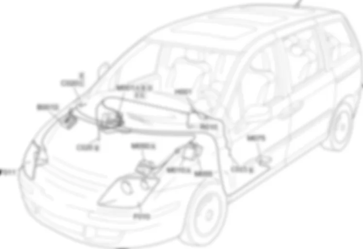
| Component code | Description | Reference to the assembly |
| B001 | ENGINE COMPARTMENT JUNCTION UNIT | Op.5505AMULTIFUNCTION COMPONENTS |
| C015 | DRIVER''S DASHBOARD EARTH | - |
| C020 | PASSENGER SIDE DASHBOARD EARTH | - |
| D001 | FRONT/DASHBOARD COUPLING | - |
| F010 | LEFT HEADLAMP | |
| F011 | RIGHT HEADLAMP | |
| H001 | Ignition switch | Op.5520AIGNITION SWITCH |
| M001 | BODY COMPUTER | |
| M010 | ENGINE MANAGEMENT CONTROL UNIT | |
| M050 | ABS CONTROL UNIT | |
| M051 | CENTRALINA IMPIANTO FRENANTE | - |
| M055 | AUTOMATIC TRANSMISSION CONTROL UNIT | - |
| M075 | ADDITIONAL HEATER CONTROL UNIT | - |
| R010 | MULTIPLE DIAGNOSTIC COUPLING | - |
| Component code | Description | Reference to the assembly |
| B001 | ENGINE COMPARTMENT JUNCTION UNIT | Op.5505AMULTIFUNCTION COMPONENTS |
| C015 | DRIVER''S DASHBOARD EARTH | - |
| C020 | PASSENGER SIDE DASHBOARD EARTH | - |
| D001 | FRONT/DASHBOARD COUPLING | - |
| F010 | LEFT HEADLAMP | |
| F011 | RIGHT HEADLAMP | |
| H001 | Ignition switch | Op.5520AIGNITION SWITCH |
| M001 | BODY COMPUTER | |
| M010 | ENGINE MANAGEMENT CONTROL UNIT | |
| M050 | ABS CONTROL UNIT | |
| M051 | - | |
| M055 | AUTOMATIC TRANSMISSION CONTROL UNIT | - |
| M075 | ADDITIONAL HEATER CONTROL UNIT | - |
| R010 | MULTIPLE DIAGNOSTIC COUPLING | - |
The car is fitted with numerous electronic control units that perform a self-diagnostic function.When a diagnostic tester (Examiner or other device) is connected to these control units, self-diagnosis data can be read (parameters, errors) or the available active diagnostic tests can be carried out.All the diagnostic lines reach the EOBD connector (European On Board Diagnosis) which conforms with the Directive in forceNodes connected to the network are diagnosed via the CAN network, while the dynamic car control network is diagnosed by a specific K lines.The following are monitored via individual diagnostic K lines:
Diagnostic socket R010 receives a power supply (pins 1 and 16) from the Body computer node M001 (pin 1 connector G and pin 5 connector D respectively) with which it communicates via the CAN and the K line: pins 6 and 14 (K line) are connected with pins 8 and 10 of connector G and pins 8 and 3 with pins 33 and 31 of connector E (respectively).The following K lines are connected to socket R010:- at pin 13, pins 5 of the left headlamp F010 and the right headlamp F011;- at pin 12, pin 11 of connector A of the ABS/ESP control unit M050;- at pin 7, pin B4 of connector A of the engine management control unit M010, pin 1 of the additional heater control unit M075 and pin 18 of the automatic transmission control unit M055.


