Wiring Diagram - CENTRAL LOCKING - Fiat ULYSSE 2.2 16V JTD fino a 04/03
Components - CENTRAL LOCKING - Fiat ULYSSE 2.2 16V JTD fino a 04/03
| Component code | Description | Reference to the assembly |
| B005 | MAXI FUSE box | - |
| B098 | Additional fuse box | - |
| C015 | Driver''s dashboard earth | - |
| C020 | Passenger dashboard earth | - |
| C030 | Left rear earth | - |
| C031 | Right rear earth | - |
| D020 | Dashboard/rear coupling | - |
| D030 | Left front door coupling | - |
| D031 | Right front door coupling | - |
| D042 | Courtesy light coupling | - |
| D085 | Rear/tailgate coupling | - |
| D196 | Left sliding door coupling | 5505A |
| D197 | Right sliding door coupling | 5505A |
| I011 | Boot release switch | 7015B |
| I018 | Switch on left rear door | - |
| I019 | Switch on right rear door | - |
| I110 | Door closing switch | - |
| J136 | Child lock relay | - |
| M001 | Body computer | 5505A |
| M093 | Steering wheel node control unit (NVO) | 5550A |
| M171 | Sliding side door node | 5505A |
| N050 | Left front door lock geared motor | 7005N |
| N051 | Right front door lock geared motor | 7005N |
| N055 | Left rear door lock geared motor | 7020N |
| N056 | Right rear door lock geared motor | 7020N |
| N057 | Boot lock geared motor | - |
| N151 | Left rear door child lock motor | - |
| N152 | Right rear door child lock motor | - |
| N166 | Left sliding side door lock geared motor | 7020N |
| N167 | Right sliding side door lock geared motor | 7020N |
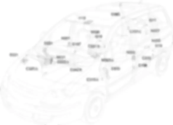
Location Components - CENTRAL LOCKING - Fiat ULYSSE 2.2 16V JTD fino a 04/03
Components - CENTRAL LOCKING - Fiat ULYSSE 2.2 16V JTD fino a 04/03
| Component code | Description | Reference to the assembly |
| B005 | MAXI FUSE box | - |
| B098 | Additional fuse box | - |
| C015 | Driver''s dashboard earth | - |
| C020 | Passenger dashboard earth | - |
| C030 | Left rear earth | - |
| C031 | Right rear earth | - |
| D020 | Dashboard/rear coupling | - |
| D030 | Left front door coupling | - |
| D031 | Right front door coupling | - |
| D042 | Courtesy light coupling | - |
| D085 | Rear/tailgate coupling | - |
| D196 | Left sliding door coupling | 5505A |
| D197 | Right sliding door coupling | 5505A |
| I011 | Boot release switch | 7015B |
| I018 | Switch on left rear door | - |
| I019 | Switch on right rear door | - |
| I110 | Door closing switch | - |
| J136 | Child lock relay | - |
| M001 | Body computer | 5505A |
| M093 | Steering wheel node control unit (NVO) | 5550A |
| M171 | Sliding side door node | 5505A |
| N050 | Left front door lock geared motor | 7005N |
| N051 | Right front door lock geared motor | 7005N |
| N055 | Left rear door lock geared motor | 7020N |
| N056 | Right rear door lock geared motor | 7020N |
| N057 | Boot lock geared motor | - |
| N151 | Left rear door child lock motor | - |
| N152 | Right rear door child lock motor | - |
| N166 | Left sliding side door lock geared motor | 7020N |
| N167 | Right sliding side door lock geared motor | 7020N |
Description - CENTRAL LOCKING - Fiat ULYSSE 2.2 16V JTD fino a 04/03
The simultaneous operation of the door locks takes place via:
Operational Description - CENTRAL LOCKING - Fiat ULYSSE 2.2 16V JTD fino a 04/03
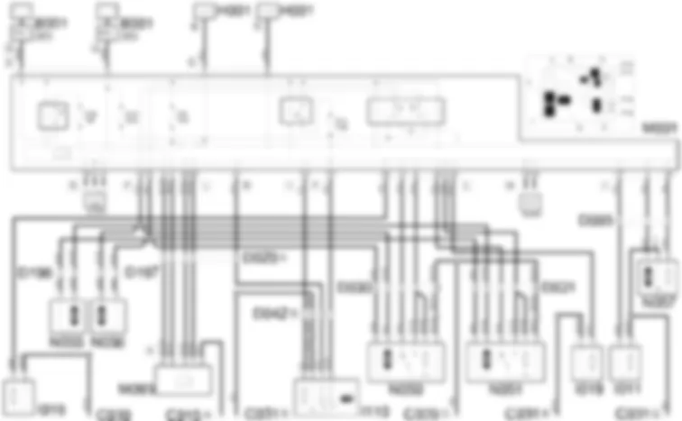
The central locking is managed by the body computer node M001.The steering wheel node M093 receives the door open/closed signal from the remote control.The command (door opening or closing) is provided by the steering wheel node control unit M093 to the body computer node M001. The signal travels via the CAN which connects the two control units.The steering wheel node control unit M093 receives a supply (pin 5 connector A) through the line protected by fuse F11, located in the body computer node M001; it receives a supply via the CAN (pin 6 connector A) from the line protected by fuse F16, located in the body computer node M001.The command for opening/closing the doors can also be sent by the internal switch I110.Pressing the special switch on unit I110 sends an earth signal indicating that the locks have been locked/unlocked from pin 6 to the body computer node M001 (pin 14 connector I).Pins 1 and 4 of I110 receive a power supply to light up the LEDs at pin 9 connector D and at pin 12 connector F of the body computer node M001; the supply provided by pin 12 connector F of M001 is protected by fuse F12 and operated by a specific relay, both housed inside the body computer node.The body computer node M001 sends supplies, from pins 13 and 15 connector F, to the electric motors for the door locks N055, N056, N050, and N051 opening or closing the doors depending on the command received.The front door locks N050 and N051 communicate, from pin 4, with the body computer M001, at pins 27 and 29 of connector L, informing it of the state of the door (locked/unlocked). The locks inform the body computer node, from pin 6, of the door status (open/closed) at pins 4 and 5.The opening of the sliding side doors is signalled by specific switches I018 (left sliding side door) and I019 (right sliding side door) to pin 34 (left door) and 33 (right door) of connector L of M001.The electric boot lock N057 is controlled by the body computer node M001 by pin 2 connector I and the boot closed signal is provided by pin 3 N057 to pin 16 connector I of the body computer node.The body computer node M001 receives the signal coming from the boot switch I011 at pin 17 of this connector.

