AUTOMOTIVE ELECTRICIANS PORTAL

Wiring diagrams Volks Wagen 2.5l diesel engine , CEBA,CEBB,CECA,CECB

Wiring diagrams Volks Wagen 2.5l diesel engine , CEBA,CEBB,CECA,CECB From May 2009

Crafter Current Flow Diagram No.  167 / 1
05.2012
Crafter Current Flow Diagram No.  167 / 2
Wiring diagrams Volks Wagen
2.5l diesel engine , CEBA,CEBB,CECA,CECB https://portal-diagnostov.com/license.html
https://portal-diagnostov.com/license.html Automotive Electricians Portal FZCO Automotive Electricians Portal FZCO
Download PDF file
ws = white
sw = black
ro = red
rt = red
br = brown
gn = green
bl = blue
gr = grey
li = purple
vi = purple
ge = yellow
or = orange
rs = pink


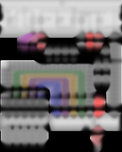
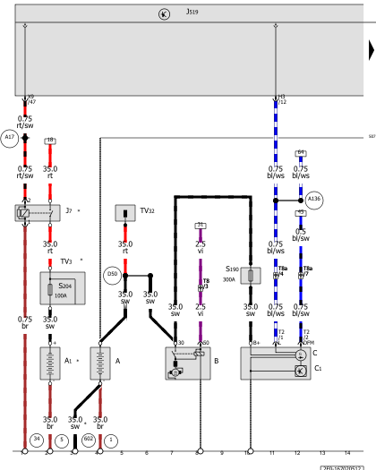
Battery, Second battery, Starter, Alternator
A -   Battery
A1 -   Second battery
B -   Starter
C -   Alternator
C1 -   Voltage regulator
J7 -   Battery isolation relayK00590313803#BTJ7
J519 -   Onboard supply control unitK00590313805#BTJ519
S190 -   Terminal 30 voltage supply fuse, in alternator wire
S204 -   Fuse 1 (30)K00590313802#BTS204
T2 -   2-pin connector
T8 -   8-pin connector, on left in engine compartmentK00590313806#BTT8
T8a -   8-pin connector, on left in engine compartmentK00590313806#BTT8a
TV3 -   Terminal 30a wiring junction, under driver seat
TV32 -   Jump start connection
  1 -   Earth strap, battery - bodyK00590313801#VB1
  5 -   Earth strap, second battery - bodyK00590313801#VB5
  34 -   Earth point, under driver seatK00590313801#VB34
  507 -   Threaded connection (30), on battery fuse holder
  602 -   Earth point, in front left footwellK00590313801#VB602
  A17 -   Connection (61), in dash panel wiring harness
  A136 -   Connection 2 (61) in dash panel wiring harness
  D50 -   Positive connection (30), in engine compartment wiring harness
* -   According to equipment

Crafter Current Flow Diagram No.  167 / 3
https://portal-diagnostov.com/license.html
https://portal-diagnostov.com/license.html Automotive Electricians Portal FZCO Automotive Electricians Portal FZCO
Get access to all wiring diagrams of the carDownload PDF file
ws = white
sw = black
ro = red
rt = red
br = brown
gn = green
bl = blue
gr = grey
li = purple
vi = purple
ge = yellow
or = orange
rs = pink


Terminal 15 relief relay, Fuse 14 on fuse holder C, Fuse 18 on fuse holder C, Fuel filter heater
J404 -   Terminal 15 relief relayK00590313803#BTJ404
J519 -   Onboard supply control unitK00590313805#BTJ519
J681 -   Terminal 15 voltage supply relay 2K00590313803#BTJ681
SA1 -   Fuse 1 in fuse holder AK00590313802#BTSA-
SB2 -   Fuse 2 on fuse holder BK00590313802#BTSB-
SA2 -   Fuse 2 in fuse holder AK00590313802#BTSA-
SA3 -   Fuse 3 in fuse holder AK00590313802#BTSA-
SA4 -   Fuse 4 in fuse holder AK00590313802#BTSA-
SA5 -   Fuse 5 in fuse holder AK00590313802#BTSA-
SD7 -   Fuse 7 on fuse holder DK00590313802#BTSD-
SA7 -   Fuse 7 in fuse holder AK00590313802#BTSA-
SC14 -   Fuse 14 on fuse holder CK00590313802#BTSC-
SC18 -   Fuse 18 on fuse holder CK00590313802#BTSC-
SD20 -   Fuse 20 on fuse holder DK00590313802#BTSD-
SC21 -   Fuse 21 on fuse holder CK00590313802#BTSC-
T2k -   2-pin connector
Z57 -   Fuel filter heater
  34 -   Earth point, under driver seatK00590313801#VB34
  507 -   Threaded connection (30), on battery fuse holder
  A1 -   Positive connection (30a), in dash panel wiring harness
  A2 -   Positive connection (15), in dash panel wiring harness
  A32 -   Positive connection (30), in dash panel wiring harness

Crafter Current Flow Diagram No.  167 / 4
https://portal-diagnostov.com/license.html
https://portal-diagnostov.com/license.html Automotive Electricians Portal FZCO Automotive Electricians Portal FZCO
Get access to all wiring diagrams of the carDownload PDF file
ws = white
sw = black
ro = red
rt = red
br = brown
gn = green
bl = blue
gr = grey
li = purple
vi = purple
ge = yellow
or = orange
rs = pink


Terminal 50 voltage supply relay, Engine component current supply relay
J179 -   Automatic glow period control unitK00590313804#BTJ179
J519 -   Onboard supply control unitK00590313805#BTJ519
J682 -   Terminal 50 voltage supply relayK00590313803#BTJ682
J757 -   Engine component current supply relayK00590313803#BTJ757
Q10 -   Glow plug 1
Q11 -   Glow plug 2
Q12 -   Glow plug 3
Q13 -   Glow plug 4
Q14 -   Glow plug 5
SC3 -   Fuse 3 on fuse holder CK00590313802#BTSC-
SC16 -   Fuse 16 on fuse holder CK00590313802#BTSC-
SC23 -   Fuse 23 on fuse holder CK00590313802#BTSC-
T8 -   8-pin connectorK00590313806#BTT8
T8g -   8-pin connector, on left of cylinder headK00590313806#BTT8g
  655 -   Earth point, on left headlightK00590313801#VB655
  B146 -   Positive connection 1 (87), in interior wiring harness
* -   From May 2010

Crafter Current Flow Diagram No.  167 / 5
https://portal-diagnostov.com/license.html
https://portal-diagnostov.com/license.html Automotive Electricians Portal FZCO Automotive Electricians Portal FZCO
Get access to all wiring diagrams of the carDownload PDF file
ws = white
sw = black
ro = red
rt = red
br = brown
gn = green
bl = blue
gr = grey
li = purple
vi = purple
ge = yellow
or = orange
rs = pink


Lambda probe, Fuse 9 on fuse holder C
G39 -   Lambda probe
J17 -   Fuel pump relayK00590313803#BTJ17
J179 -   Automatic glow period control unitK00590313804#BTJ179
J519 -   Onboard supply control unitK00590313805#BTJ519
J623 -   Engine control unitK00590313804#BTJ623
SC6 -   Fuse 6 on fuse holder CK00590313802#BTSC-
SC8 -   Fuse 8 on fuse holder CK00590313802#BTSC-
SC9 -   Fuse 9 on fuse holder CK00590313802#BTSC-
T6ar -   6-pin connector
T9 -   9-pin connector, on left in engine compartmentK00590313806#BTT9
T94 -   94-pin connector
Z19 -   Lambda probe heater
  655 -   Earth point, on left headlightK00590313801#VB655
  B147 -   Positive connection 2 (87), in interior wiring harness
  B148 -   Positive connection 3 (87), in interior wiring harness
  D113 -   Connection 11 in engine compartment wiring harness
* -   Only models with stop/start system

Crafter Current Flow Diagram No.  167 / 6
https://portal-diagnostov.com/license.html
https://portal-diagnostov.com/license.html Automotive Electricians Portal FZCO Automotive Electricians Portal FZCO
Get access to all wiring diagrams of the carDownload PDF file
ws = white
sw = black
ro = red
rt = red
br = brown
gn = green
bl = blue
gr = grey
li = purple
vi = purple
ge = yellow
or = orange
rs = pink


Throttle valve potentiometer, Oil level and oil temperature sender, Throttle valve module, Fuel metering valve, Intake manifold flap motor
G69 -   Throttle valve potentiometer
G266 -   Oil level and oil temperature sender
J338 -   Throttle valve module
J519 -   Onboard supply control unitK00590313805#BTJ519
J623 -   Engine control unitK00590313804#BTJ623
N290 -   Fuel metering valve
SC10 -   Fuse 10 on fuse holder CK00590313802#BTSC-
T3 -   3-pin connectorK00590313806#BTT3
T3a -   3-pin connector
T5 -   5-pin connector
T8 -   8-pin connectorK00590313806#BTT8
T8a -   8-pin connectorK00590313806#BTT8a
T8g -   8-pin connector, on left of cylinder headK00590313806#BTT8g
T60 -   60-pin connector
T94 -   94-pin connector
V157 -   Intake manifold flap motor
  85 -   Earth connection 1, in engine compartment wiring harness
  655 -   Earth point, on left headlightK00590313801#VB655
  B147 -   Positive connection 2 (87), in interior wiring harness
  D101 -   Connection 1 in engine compartment wiring harness
  D102 -   Connection 2 in engine compartment wiring harness
* -   From May 2010

Crafter Current Flow Diagram No.  167 / 7
https://portal-diagnostov.com/license.html
https://portal-diagnostov.com/license.html Automotive Electricians Portal FZCO Automotive Electricians Portal FZCO
Get access to all wiring diagrams of the carDownload PDF file
ws = white
sw = black
ro = red
rt = red
br = brown
gn = green
bl = blue
gr = grey
li = purple
vi = purple
ge = yellow
or = orange
rs = pink


Engine speed sender, Fuel temperature sender, Fuel pressure sender
G28 -   Engine speed sender
G81 -   Fuel temperature sender
G212 -   Exhaust gas recirculation potentiometer
G247 -   Fuel pressure sender
J519 -   Onboard supply control unitK00590313805#BTJ519
J623 -   Engine control unitK00590313804#BTJ623
N18 -   Exhaust gas recirculation valve
T3c -   3-pin connector, on left of cylinder head
T6 -   6-pin connectorK00590313806#BTT6
T60 -   60-pin connector
  D101 -   Connection 1 in engine compartment wiring harness
  D102 -   Connection 2 in engine compartment wiring harness

Crafter Current Flow Diagram No.  167 / 8
https://portal-diagnostov.com/license.html
https://portal-diagnostov.com/license.html Automotive Electricians Portal FZCO Automotive Electricians Portal FZCO
Get access to all wiring diagrams of the carDownload PDF file
ws = white
sw = black
ro = red
rt = red
br = brown
gn = green
bl = blue
gr = grey
li = purple
vi = purple
ge = yellow
or = orange
rs = pink


Charge pressure sender, Hall sender, Intake air temperature sender, Coolant temperature sender, Injector, cylinder 1
G31 -   Charge pressure sender
G40 -   Hall sender
G42 -   Intake air temperature sender
G62 -   Coolant temperature sender
J519 -   Onboard supply control unitK00590313805#BTJ519
J623 -   Engine control unitK00590313804#BTJ623
N30 -   Injector, cylinder 1
T3b -   3-pin connector, on engine blockK00590313806#BTT3b
T4 -   4-pin connector
T9 -   9-pin connectorK00590313806#BTT9
T60 -   60-pin connector
T94 -   94-pin connector
* -   From May 2010

Crafter Current Flow Diagram No.  167 / 9
https://portal-diagnostov.com/license.html
https://portal-diagnostov.com/license.html Automotive Electricians Portal FZCO Automotive Electricians Portal FZCO
Get access to all wiring diagrams of the carDownload PDF file
ws = white
sw = black
ro = red
rt = red
br = brown
gn = green
bl = blue
gr = grey
li = purple
vi = purple
ge = yellow
or = orange
rs = pink


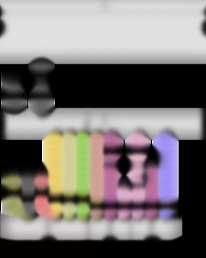
Injector, cylinder 2, Injector, cylinder 3, Injector, cylinder 4, Charge pressure control solenoid valve, Injector, cylinder 5
J519 -   Onboard supply control unitK00590313805#BTJ519
J623 -   Engine control unitK00590313804#BTJ623
N31 -   Injector, cylinder 2
N32 -   Injector, cylinder 3
N33 -   Injector, cylinder 4
N75 -   Charge pressure control solenoid valve
N83 -   Injector, cylinder 5
T8a -   8-pin connector, on left in engine compartmentK00590313806#BTT8a
T60 -   60-pin connector

Crafter Current Flow Diagram No.  167 / 10
https://portal-diagnostov.com/license.html
https://portal-diagnostov.com/license.html Automotive Electricians Portal FZCO Automotive Electricians Portal FZCO
Get access to all wiring diagrams of the carDownload PDF file
ws = white
sw = black
ro = red
rt = red
br = brown
gn = green
bl = blue
gr = grey
li = purple
vi = purple
ge = yellow
or = orange
rs = pink


Gearbox neutral position switch, Clutch pedal switch 2, Accelerator position sender, Coolant circuit valve
F365 -   Gearbox neutral position switch
F379 -   Clutch pedal switch 2
G79 -   Accelerator position sender
J519 -   Onboard supply control unitK00590313805#BTJ519
J623 -   Engine control unitK00590313804#BTJ623
N214 -   Coolant circuit valve
T2d -   2-pin connector
T6a -   6-pin connectorK00590313807#BTT6a
T94 -   94-pin connector
  639 -   Earth point, left A-pillarK00590313801#VB639
* -   Only models with stop/start system

Crafter Current Flow Diagram No.  167 / 11
https://portal-diagnostov.com/license.html
https://portal-diagnostov.com/license.html Automotive Electricians Portal FZCO Automotive Electricians Portal FZCO
Get access to all wiring diagrams of the carDownload PDF file
ws = white
sw = black
ro = red
rt = red
br = brown
gn = green
bl = blue
gr = grey
li = purple
vi = purple
ge = yellow
or = orange
rs = pink


Main switch for stop/start system, Clutch pedal switch, Bonnet contact switch
E101 -   Main switch for stop/start system
F36 -   Clutch pedal switch
F266 -   Bonnet contact switch
J519 -   Onboard supply control unitK00590313805#BTJ519
J623 -   Engine control unitK00590313804#BTJ623
T2gp -   2-pin connector
T10d -   10-pin connector
T28 -   28-pin connectorK00590313806#BTT28
T94 -   94-pin connector
  43 -   Earth point, lower part of right A-pillarK00590313801#VB43
  639 -   Earth point, left A-pillarK00590313801#VB639
  B340 -   Connection 1 (58d), in main wiring harness
* -   Only models with stop/start system

Crafter Current Flow Diagram No.  167 / 12
https://portal-diagnostov.com/license.html
https://portal-diagnostov.com/license.html Automotive Electricians Portal FZCO Automotive Electricians Portal FZCO
Get access to all wiring diagrams of the carDownload PDF file
ws = white
sw = black
ro = red
rt = red
br = brown
gn = green
bl = blue
gr = grey
li = purple
vi = purple
ge = yellow
or = orange
rs = pink


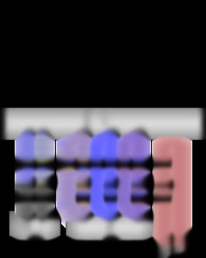
Air mass meter, Intake manifold pressure sender, Exhaust gas pressure sensor 1
G70 -   Air mass meter
G71 -   Intake manifold pressure sender
G450 -   Exhaust gas pressure sensor 1
J519 -   Onboard supply control unitK00590313805#BTJ519
J623 -   Engine control unitK00590313804#BTJ623
T3d -   3-pin connector
T3f -   3-pin connector
T4a -   4-pin connector
T94 -   94-pin connector
  B135 -   Connection 1 (15a), in interior wiring harness
  D103 -   Connection 3 in engine compartment wiring harness
  D106 -   Connection 4 in engine compartment wiring harness
* -   Only models with stop/start system

Crafter Current Flow Diagram No.  167 / 13
https://portal-diagnostov.com/license.html
https://portal-diagnostov.com/license.html Automotive Electricians Portal FZCO Automotive Electricians Portal FZCO
Get access to all wiring diagrams of the carDownload PDF file
ws = white
sw = black
ro = red
rt = red
br = brown
gn = green
bl = blue
gr = grey
li = purple
vi = purple
ge = yellow
or = orange
rs = pink


Brake light switch, Brake pedal switch, Continued coolant circulation relay, Coolant circulation pump
F -   Brake light switch
F63 -   Brake pedal switch
J104 -   ABS control unitK00590313804#BTJ104
J151 -   Continued coolant circulation relay, under driver seatK00590313803#BTJ151
J519 -   Onboard supply control unitK00590313805#BTJ519
J623 -   Engine control unitK00590313804#BTJ623
T4c -   4-pin connector
T28 -   28-pin connector, on lower section of right A-pillarK00590313806#BTT28
T38 -   38-pin connector
T46 -   46-pin connector
T94 -   94-pin connector
V50 -   Coolant circulation pump
  640 -   Earth point 2, left in engine compartmentK00590313801#VB640
  A89 -   Connection 2 (54) in dash panel wiring harness
  B149 -   Positive connection 2 (15a), in interior wiring harness
* -   Only models with anti-lock brake system (ABS) and electronic stabilisation program (ESP)
*2 -   From November 2009

Crafter Current Flow Diagram No.  167 / 14
https://portal-diagnostov.com/license.html
https://portal-diagnostov.com/license.html Automotive Electricians Portal FZCO Automotive Electricians Portal FZCO
Get access to all wiring diagrams of the carDownload PDF file
ws = white
sw = black
ro = red
rt = red
br = brown
gn = green
bl = blue
gr = grey
li = purple
vi = purple
ge = yellow
or = orange
rs = pink


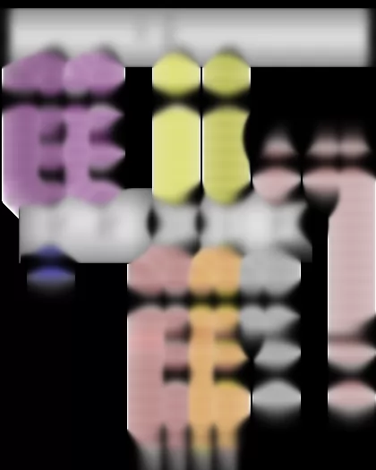
Fuel gauge sender, Fuel system pressurisation pump, Coolant pump relay, Wiring junction 1 for bus systems, Diagnostic connection
G -   Fuel gauge sender
G6 -   Fuel system pressurisation pump
J235 -   Coolant pump relay, on driver seatK00590313803#BTJ235
J301 -   Air conditioning system control unit
J364 -   Auxiliary heater control unit
J623 -   Engine control unitK00590313804#BTJ623
T2fa -   2-pin connector
T3e -   3-pin connector
T4b -   4-pin connector
T8b -   8-pin connectorK00590313807#BTT8b
T8t -   8-pin connector
T12c -   12-pin connector
T16 -   16-pin connector
TV26 -   Wiring junction 1 for bus systemsK00590313806#BTTV26
T28 -   28-pin connector, on lower section of right A-pillarK00590313806#BTT28
T94 -   94-pin connector
U31 -   Diagnostic connection
  34 -   Earth point, under driver seatK00590313801#VB34
  65 -   Earth point, on rear of left longitudinal memberK00590313801#VB65
  638 -   Earth point, on right A-pillarK00590313801#VB638
  639 -   Earth point, left A-pillarK00590313801#VB639
  704 -   Earth point 2 under driver seatK00590313801#VB704
* -   From May 2010
*2 -   Only models with air conditioning system
*3 -   Only models with no air conditioning system
*4 -   From November 2009

Crafter Current Flow Diagram No.  167 / 15
https://portal-diagnostov.com/license.html
https://portal-diagnostov.com/license.html Automotive Electricians Portal FZCO Automotive Electricians Portal FZCO
Get access to all wiring diagrams of the carDownload PDF file
ws = white
sw = black
ro = red
rt = red
br = brown
gn = green
bl = blue
gr = grey
li = purple
vi = purple
ge = yellow
or = orange
rs = pink


Pressure sender for reducing agent metering system, Injector for reducing agent
G686 -   Pressure sender for reducing agent metering system
J623 -   Engine control unitK00590313804#BTJ623
N474 -   Injector for reducing agent
T1aa -   Single connector
T2gt -   2-pin connector
T2gu -   2-pin connector
T3ai -   3-pin connector
T10s -   10-pin connectorK00590313807#BTT10s
T94 -   94-pin connector
  34 -   Earth point, under driver seatK00590313801#VB34
  611 -   Earth connection, on fuel tank filler neck
* -   Only panel van and Kombi models
*2 -   Only models with double cab/ dropside

Crafter Current Flow Diagram No.  167 / 16
https://portal-diagnostov.com/license.html
https://portal-diagnostov.com/license.html Automotive Electricians Portal FZCO Automotive Electricians Portal FZCO
Get access to all wiring diagrams of the carDownload PDF file
ws = white
sw = black
ro = red
rt = red
br = brown
gn = green
bl = blue
gr = grey
li = purple
vi = purple
ge = yellow
or = orange
rs = pink


Exhaust gas temperature sender 1, Exhaust gas temperature sender 3, Exhaust gas temperature sender 4, Control unit for NOx sender
G235 -   Exhaust gas temperature sender 1
G295 -   NOx sender
G495 -   Exhaust gas temperature sender 3
G648 -   Exhaust gas temperature sender 4
J583 -   Control unit for NOx senderK00590313805#BTJ583
J623 -   Engine control unitK00590313804#BTJ623
T2a -   2-pin connectorK00590313806#BTT2a
T2aw -   2-pin connectorK00590313807#BTT2aw
T2c -   2-pin connectorK00590313806#BTT2c
T3 -   3-pin connectorK00590313806#BTT3
T5g -   5-pin connector
T8a -   8-pin connectorK00590313806#BTT8a
T94 -   94-pin connector
  732 -   Earth point 3 under driver seatK00590313801#VB732
  D107 -   Connection 5 in engine compartment wiring harness

Crafter Current Flow Diagram No.  167 / 17
https://portal-diagnostov.com/license.html
https://portal-diagnostov.com/license.html Automotive Electricians Portal FZCO Automotive Electricians Portal FZCO
Get access to all wiring diagrams of the carDownload PDF file
ws = white
sw = black
ro = red
rt = red
br = brown
gn = green
bl = blue
gr = grey
li = purple
vi = purple
ge = yellow
or = orange
rs = pink


Position sender for charge pressure positioner, Control unit for reducing-agent heater, Heater element for crankcase breather, Fuel pressure regulating valve
G581 -   Position sender for charge pressure positioner
J623 -   Engine control unitK00590313804#BTJ623
J891 -   Control unit for reducing-agent heaterK00590313805#BTJ891
N79 -   Heater element for crankcase breather
N276 -   Fuel pressure regulating valve
T2gs -   2-pin connector
T3ak -   3-pin connector
T4bg -   4-pin connector
T8 -   8-pin connector, on left in engine compartmentK00590313806#BTT8
T9c -   9-pin connectorK00590313807#BTT9c
T60 -   60-pin connector
T94 -   94-pin connector
* -   Only panel van and Kombi models
*2 -   Only for countries with cold climate
*3 -   Only models with double cab/ dropside

Crafter Current Flow Diagram No.  167 / 18
https://portal-diagnostov.com/license.html
https://portal-diagnostov.com/license.html Automotive Electricians Portal FZCO Automotive Electricians Portal FZCO
Get access to all wiring diagrams of the carDownload PDF file
ws = white
sw = black
ro = red
rt = red
br = brown
gn = green
bl = blue
gr = grey
li = purple
vi = purple
ge = yellow
or = orange
rs = pink


Temperature sender for reducing agent, Control unit for reducing-agent heater, Fuse 34 on fuse holder D, Fuse 35 on fuse holder D, Heater for reducing-agent line (heater circuit 2)
G685 -   Temperature sender for reducing agent
J891 -   Control unit for reducing-agent heaterK00590313805#BTJ891
SD34 -   Fuse 34 on fuse holder DK00590313802#BTSD-
SD35 -   Fuse 35 on fuse holder DK00590313802#BTSD-
T2au -   2-pin connectorK00590313807#BTT2au
T4bh -   4-pin connectorK00590313807#BTT4bh
T5e -   5-pin connector
T9c -   9-pin connectorK00590313807#BTT9c
T10s -   10-pin connectorK00590313807#BTT10s
Z102 -   Heater for reducing-agent tank (heater circuit 1)
Z104 -   Heater for reducing-agent line (heater circuit 2)
  65 -   Earth point, on rear of left longitudinal memberK00590313801#VB65
  732 -   Earth point 3 under driver seatK00590313801#VB732
  D110 -   Connection 8 in engine compartment wiring harness
* -   Only models with double cab/ dropside
*2 -   Only panel van and Kombi models

Crafter Current Flow Diagram No.  167 / 19
https://portal-diagnostov.com/license.html
https://portal-diagnostov.com/license.html Automotive Electricians Portal FZCO Automotive Electricians Portal FZCO
Get access to all wiring diagrams of the carDownload PDF file
ws = white
sw = black
ro = red
rt = red
br = brown
gn = green
bl = blue
gr = grey
li = purple
vi = purple
ge = yellow
or = orange
rs = pink


Reducing agent level sender, Evaluation unit for reducing agent level, Control unit for reducing-agent heater, Pump for reducing agent, Heater for reducing-agent pump (heater circuit 2)
G697 -   Reducing agent level sender
G698 -   Evaluation unit for reducing agent level
J891 -   Control unit for reducing-agent heaterK00590313805#BTJ891
T3ah -   3-pin connector
T5e -   5-pin connector
T5f -   5-pin connector
T9c -   9-pin connectorK00590313807#BTT9c
T10s -   10-pin connectorK00590313807#BTT10s
V437 -   Pump for reducing agent
Z103 -   Heater for reducing-agent pump (heater circuit 2)
  65 -   Earth point, on rear of left longitudinal memberK00590313801#VB65
  732 -   Earth point 3 under driver seatK00590313801#VB732
  D108 -   Connection 6 in engine compartment wiring harness
  D110 -   Connection 8 in engine compartment wiring harness
  D111 -   Connection 9 in engine compartment wiring harness
  D112 -   Connection 10 in engine compartment wiring harness
* -   Only panel van and Kombi models
*2 -   Only models with double cab/ dropside
*3 -   Only models with stop/start system

Crafter Current Flow Diagram No.  167 / 20
https://portal-diagnostov.com/license.html
https://portal-diagnostov.com/license.html Automotive Electricians Portal FZCO Automotive Electricians Portal FZCO
Get access to all wiring diagrams of the carDownload PDF file
ws = white
sw = black
ro = red
rt = red
br = brown
gn = green
bl = blue
gr = grey
li = purple
vi = purple
ge = yellow
or = orange
rs = pink


Oil pressure switch, Control unit in dash panel insert, Dash panel insert, Reversing valve for reducing agent
F1 -   Oil pressure switch
G1 -   Fuel gauge
G3 -   Coolant temperature gauge
H3 -   Buzzer and gong
J285 -   Control unit in dash panel insert
K -   Dash panel insertK00590313805#BTK
K3 -   Oil pressure warning lamp
K28 -   Coolant temperature and coolant shortage warning lamp
K38 -   Oil level warning lamp
K105 -   Reserve fuel warning lamp
K231 -   Diesel particulate filter warning lamp
N473 -   Reversing valve for reducing agent
T2av -   2-pin connector
T8a -   8-pin connector, on left in engine compartmentK00590313806#BTT8a
T9c -   9-pin connectorK00590313807#BTT9c
T10 -   10-pin connector, on lower section of right A-pillarK00590313806#BTT10
T18a -   18-pin connector
T28 -   28-pin connectorK00590313806#BTT28
  43 -   Earth point, lower part of right A-pillarK00590313801#VB43
  A20 -   Positive connection (15a), in dash panel wiring harness
  D111 -   Connection 9 in engine compartment wiring harness
* -   From April 2011
*2 -   Only panel van and Kombi models
*3 -   Only models with double cab/ dropside