AUTOMOTIVE ELECTRICIANS PORTAL

Wiring diagrams Volks Wagen1.4 l/103 kW Motronic, engine code BMY

Wiring diagrams Volks Wagen1.4 l/103 kW Motronic, engine code BMY from February 2006
Touran Current Flow Diagram No.  109 / 1
Edition 10.2006
Notes:
For information concerning
t  Position of relays and fuses
t  Multi-pin connections
t  Control units and relays
t  Earth connections
→ List of Fitting Locations!
For information concerning
t  Fault Finding Programs
→ guided fault finding

Touran Current Flow Diagram No.  109 / 2
Wiring diagrams Volks Wagen1.4 l/103 kW Motronic, engine code BMY https://portal-diagnostov.com/license.html
https://portal-diagnostov.com/license.html Automotive Electricians Portal FZCO Automotive Electricians Portal FZCO
Download PDF file
ws = white
sw = black
ro = red
rt = red
br = brown
gn = green
bl = blue
gr = grey
li = purple
vi = purple
ge = yellow
or = orange
rs = pink


Battery, alternator, starter, fuses
A -   Battery
B -   Starter
C -   Alternator
C1 -   Voltage regulator
J519 -   Onboard supply control unitK00589750804#BTJ519
SA1 -   Fuse 1 on fuse holder A
SA5 -   Fuse 5 on fuse holder A
SC43 -   Fuse 43 on fuse holder C
T2 -   2-pin connector
T2c -   2-pin connector, near starter (in models without air conditioning system)K00589750806#BTT2c
T4t -   4-pin connector, near starter (in models with air conditioning system)K00589750806#BTT4t
   1 -   Earth strap, battery - bodyK00589750801#VB1
   14 -   Earth point, on gearboxK00589750801#VB14
   508 -   Screw connection (30), on electronics box
   652 -   Earth point, engine and gearbox earthK00589750801#VB652
   D50 -   Positive connection (30), in engine compartment wiring harness
* -   Models with 90 A/ 120 A alternator
** -   Models with 140 A alternator
*** -   In models without optional equipment
**** -   In models with optional equipment

Touran Current Flow Diagram No.  109 / 3
https://portal-diagnostov.com/license.html
https://portal-diagnostov.com/license.html Automotive Electricians Portal FZCO Automotive Electricians Portal FZCO
Get access to all wiring diagrams of the carDownload PDF file
ws = white
sw = black
ro = red
rt = red
br = brown
gn = green
bl = blue
gr = grey
li = purple
vi = purple
ge = yellow
or = orange
rs = pink


Terminal 50 voltage supply relay, terminal 15 voltage supply relay 2, magnetic clutch for supercharger, sensor for current measurement, fuses
G582 -   Sensor for current measurementK00589750803#BTG582
J519 -   Onboard supply control unitK00589750804#BTJ519
J681 -   Terminal 15 voltage supply relay 2K00589750803#BTJ681
J682 -   Terminal 50 voltage supply relayK00589750803#BTJ682
N421 -   Magnetic clutch for supercharger
SB20 -   Fuse 20 on fuse holder B
SB27 -   Fuse 27 on fuse holder B
SB49 -   Fuse 49 on fuse holder B
SC1 -   Fuse 1 on fuse holder C
SC2 -   Fuse 2 on fuse holder C
SC4 -   Fuse 4 on fuse holder C
SC6 -   Fuse 6 on fuse holder C
T40 -   40-pin connector
   44 -   Earth point, lower part of left A-pillarK00589750801#VB44
   399 -   Earth connection 34, in main wiring harness
   A20 -   Positive connection (15a), in dash panel wiring harness
   A41 -   Positive connection (50), in dash panel wiring harness
   A192 -   Positive connection 3 (15a), in dash panel wiring harness
   B163 -   Positive connection 1 (15), in interior wiring harness
   B277 -   Positive connection 1 (15a), in main wiring harness
   B278 -   Positive connection 2 (15a), in main wiring harness
   D113 -   Connection 11, in engine compartment wiring harness
-●-●- -   models with winter driving program only
-●●- -   only for models with flexible service interval display

Touran Current Flow Diagram No.  109 / 4
https://portal-diagnostov.com/license.html
https://portal-diagnostov.com/license.html Automotive Electricians Portal FZCO Automotive Electricians Portal FZCO
Get access to all wiring diagrams of the carDownload PDF file
ws = white
sw = black
ro = red
rt = red
br = brown
gn = green
bl = blue
gr = grey
li = purple
vi = purple
ge = yellow
or = orange
rs = pink


Fuel pump control unit, fuel gauge sender, fuel pump
G -   Fuel gauge sender
G6 -   Fuel pump
J519 -   Onboard supply control unitK00589750804#BTJ519
J538 -   Fuel pump control unit, near fuel gauge senderK00589750805#BTJ538
SB6 -   Fuse 6 on fuse holder B
SB15 -   Fuse 15 on fuse holder B
SB21 -   Fuse 21 on fuse holder B
SB24 -   Fuse 24 on fuse holder B
T5a -   5-pin connector
T10q -   10-pin connector
T40 -   40-pin connector
   369 -   Earth connection 4, in main wiring harness
   653 -   Earth point, left D-pillarK00589750801#VB653

Touran Current Flow Diagram No.  109 / 5
https://portal-diagnostov.com/license.html
https://portal-diagnostov.com/license.html Automotive Electricians Portal FZCO Automotive Electricians Portal FZCO
Get access to all wiring diagrams of the carDownload PDF file
ws = white
sw = black
ro = red
rt = red
br = brown
gn = green
bl = blue
gr = grey
li = purple
vi = purple
ge = yellow
or = orange
rs = pink


Motronic current supply relay
J271 -   Motronic current supply relay, on electronics box, in left engine compartment (100)K00589750803#BTJ271
J519 -   Onboard supply control unitK00589750804#BTJ519
SB10 -   Fuse 10 on fuse holder B
SB13 -   Fuse 13 on fuse holder B
SB14 -   Fuse 14 on fuse holder B
SB22 -   Fuse 22 on fuse holder B
SB23 -   Fuse 23 on fuse holder B
T14a -   14-pin connector, near batteryK00589750806#BTT14a
T40 -   40-pin connector
   D78 -   Positive connection 1 (30a), in engine compartment wiring harness
   D182 -   Connection 3 (87a), in engine compartment wiring harness

Touran Current Flow Diagram No.  109 / 6
https://portal-diagnostov.com/license.html
https://portal-diagnostov.com/license.html Automotive Electricians Portal FZCO Automotive Electricians Portal FZCO
Get access to all wiring diagrams of the carDownload PDF file
ws = white
sw = black
ro = red
rt = red
br = brown
gn = green
bl = blue
gr = grey
li = purple
vi = purple
ge = yellow
or = orange
rs = pink


Engine control unit
J519 -   Onboard supply control unitK00589750804#BTJ519
J527 -   Steering column electronics control unitK00589750804#BTJ527
J623 -   Engine control unit, in centre of plenum chamberK00589750804#BTJ623
T14a -   14-pin connector, near batteryK00589750806#BTT14a
T20d -   20-pin connector
T94 -   94-pin connector
   131 -   Earth connection 2, in engine compartment wiring harness
   607 -   Earth point, on left in plenum chamberK00589750801#VB607
   D78 -   Positive connection 1 (30a), in engine compartment wiring harness
   D182 -   Connection 3 (87a), in engine compartment wiring harness
   D114 -   Connection 12, in engine compartment wiring harness

Touran Current Flow Diagram No.  109 / 7
https://portal-diagnostov.com/license.html
https://portal-diagnostov.com/license.html Automotive Electricians Portal FZCO Automotive Electricians Portal FZCO
Get access to all wiring diagrams of the carDownload PDF file
ws = white
sw = black
ro = red
rt = red
br = brown
gn = green
bl = blue
gr = grey
li = purple
vi = purple
ge = yellow
or = orange
rs = pink


Engine control unit, ignition coils with output stage, spark plugs
J519 -   Onboard supply control unitK00589750804#BTJ519
J623 -   Engine control unit, in centre of plenum chamberK00589750804#BTJ623
N70 -   Ignition coil 1 with output stage
N127 -   Ignition coil 2 with output stage
N291 -   Ignition coil 3 with output stage
N292 -   Ignition coil 4 with output stage
P -   Spark plug connector
Q -   Spark plugs
T14a -   14-pin connector, near batteryK00589750806#BTT14a
T60 -   60-pin connector
   15 -   Earth point, on cylinder head
   85 -   Earth connection 1, in engine compartment wiring harness
   132 -   Earth connection 3, in engine compartment wiring harness
   281 -   Earth connection 1, in engine harness
   642 -   Earth point, electronically controlled fanK00589750801#VB642
   D206 -   Connection 4 (87a), in engine wiring harness

Touran Current Flow Diagram No.  109 / 8
https://portal-diagnostov.com/license.html
https://portal-diagnostov.com/license.html Automotive Electricians Portal FZCO Automotive Electricians Portal FZCO
Get access to all wiring diagrams of the carDownload PDF file
ws = white
sw = black
ro = red
rt = red
br = brown
gn = green
bl = blue
gr = grey
li = purple
vi = purple
ge = yellow
or = orange
rs = pink


Engine control unit, throttle valve drive, intake manifold flap potentiometer, fuel pressure sender
G186 -   Throttle valve drive, electric throttle
G187 -   Throttle valve drives angle sender 1, electric throttle
G188 -   Throttle valve drives angle sender 2, electric throttle
G247 -   Fuel pressure sender
G336 -   Intake manifold flap potentiometer
J338 -   Throttle valve module
J519 -   Onboard supply control unitK00589750804#BTJ519
J623 -   Engine control unit, in centre of plenum chamberK00589750804#BTJ623
T6x -   6-pin connector
T60 -   60-pin connector
   220 -   Earth connection (sender earth), in engine wiring harness
   D101 -   Connection 1, in engine compartment wiring harness

Touran Current Flow Diagram No.  109 / 9
https://portal-diagnostov.com/license.html
https://portal-diagnostov.com/license.html Automotive Electricians Portal FZCO Automotive Electricians Portal FZCO
Get access to all wiring diagrams of the carDownload PDF file
ws = white
sw = black
ro = red
rt = red
br = brown
gn = green
bl = blue
gr = grey
li = purple
vi = purple
ge = yellow
or = orange
rs = pink


Engine control unit, Hall sender, regulating flap control unit, regulating flap position control motor, regulating flap potentiometer, intake air temperature sender, intake manifold pressure sender
G40 -   Hall sender
G42 -   Intake air temperature sender
G71 -   Intake manifold pressure sender
G584 -   Regulating flap potentiometer
J519 -   Onboard supply control unitK00589750804#BTJ519
J623 -   Engine control unit, in centre of plenum chamberK00589750804#BTJ623
J808 -   Regulating flap control unit
T3b -   3-pin connector, on front of engine
T5z -   5-pin connector
T14a -   14-pin connector, near batteryK00589750806#BTT14a
T60 -   60-pin connector
T94 -   94-pin connector
V380 -   Regulating flap position control motor
   D101 -   Connection 1, in engine compartment wiring harness

Touran Current Flow Diagram No.  109 / 10
https://portal-diagnostov.com/license.html
https://portal-diagnostov.com/license.html Automotive Electricians Portal FZCO Automotive Electricians Portal FZCO
Get access to all wiring diagrams of the carDownload PDF file
ws = white
sw = black
ro = red
rt = red
br = brown
gn = green
bl = blue
gr = grey
li = purple
vi = purple
ge = yellow
or = orange
rs = pink


Engine control unit, intake air temperature sender 3, intake manifold pressure sender 3, charge air pressure sender, intake air temperature sender 2, engine speed sender, coolant temperature sender
G28 -   Engine speed sender
G31 -   Charge air pressure sender
G62 -   Coolant temperature sender
G299 -   Intake air temperature sender 2
G520 -   Intake air temperature sender 3
G583 -   Intake manifold pressure sender 3
J519 -   Onboard supply control unitK00589750804#BTJ519
J623 -   Engine control unit, in centre of plenum chamberK00589750804#BTJ623
T60 -   60-pin connector
   220 -   Earth connection (sender earth), in engine wiring harness
   D122 -   Connection 20, in engine compartment wiring harness
   D123 -   Connection 21, in engine compartment wiring harness

Touran Current Flow Diagram No.  109 / 11
https://portal-diagnostov.com/license.html
https://portal-diagnostov.com/license.html Automotive Electricians Portal FZCO Automotive Electricians Portal FZCO
Get access to all wiring diagrams of the carDownload PDF file
ws = white
sw = black
ro = red
rt = red
br = brown
gn = green
bl = blue
gr = grey
li = purple
vi = purple
ge = yellow
or = orange
rs = pink


Engine control unit, knock sensor, injectors
G61 -   Knock sensor 1
J519 -   Onboard supply control unitK00589750804#BTJ519
J623 -   Engine control unit, in centre of plenum chamberK00589750804#BTJ623
N30 -   Injector, cylinder 1
N31 -   Injector, cylinder 2
N32 -   Injector, cylinder 3
N33 -   Injector, cylinder 4
T60 -   60-pin connector
   D123 -   Connection 21, in engine compartment wiring harness

Touran Current Flow Diagram No.  109 / 12
https://portal-diagnostov.com/license.html
https://portal-diagnostov.com/license.html Automotive Electricians Portal FZCO Automotive Electricians Portal FZCO
Get access to all wiring diagrams of the carDownload PDF file
ws = white
sw = black
ro = red
rt = red
br = brown
gn = green
bl = blue
gr = grey
li = purple
vi = purple
ge = yellow
or = orange
rs = pink


Engine control unit, additional coolant pump relay, coolant circulation pump, charge pressure control solenoid valve, turbocharger air recirculation valve
J496 -   Additional coolant pump relayK00589750803#BTJ496
J519 -   Onboard supply control unitK00589750804#BTJ519
J623 -   Engine control unit, in centre of plenum chamberK00589750804#BTJ623
N75 -   Charge pressure control solenoid valve
N249 -   Turbocharger air recirculation valve
T4x -   4-pin connector, on lower left of radiator fan
T14a -   14-pin connector, near batteryK00589750806#BTT14a
T60 -   60-pin connector
T94 -   94-pin connector
V50 -   Coolant circulation pump
   D180 -   Connection (87a), in engine compartment wiring harness
   D181 -   Connection 2 (87a), in engine compartment wiring harness
*** -   Radiator fan connection

Touran Current Flow Diagram No.  109 / 13
https://portal-diagnostov.com/license.html
https://portal-diagnostov.com/license.html Automotive Electricians Portal FZCO Automotive Electricians Portal FZCO
Get access to all wiring diagrams of the carDownload PDF file
ws = white
sw = black
ro = red
rt = red
br = brown
gn = green
bl = blue
gr = grey
li = purple
vi = purple
ge = yellow
or = orange
rs = pink


Intake manifold flap -inlet camshaft control -activated charcoal filter system and fuel pressure valve, radiator outlet coolant temperature sender, brake servo pressure sensor
G83 -   Radiator outlet coolant temperature sender
G294 -   Brake servo pressure sensor
J519 -   Onboard supply control unitK00589750804#BTJ519
J623 -   Engine control unit, in centre of plenum chamberK00589750804#BTJ623
N80 -   Activated charcoal filter system solenoid valve 1
N205 -   Inlet camshaft control valve 1
N276 -   Fuel pressure regulating valve
N316 -   Intake manifold flap valve
T4aj -   4-pin connector
T14a -   14-pin connector, near batteryK00589750806#BTT14a
T60 -   60-pin connector
T94 -   94-pin connector
   327 -   Earth connection (sender earth), in engine compartment wiring harness
   D106 -   Connection 4, in engine compartment wiring harness
   D196 -   Connection 2 (87a), in engine wiring harness
   D207 -   Connection 7 (87a), in engine compartment wiring harness

Touran Current Flow Diagram No.  109 / 14
https://portal-diagnostov.com/license.html
https://portal-diagnostov.com/license.html Automotive Electricians Portal FZCO Automotive Electricians Portal FZCO
Get access to all wiring diagrams of the carDownload PDF file
ws = white
sw = black
ro = red
rt = red
br = brown
gn = green
bl = blue
gr = grey
li = purple
vi = purple
ge = yellow
or = orange
rs = pink


Engine control unit, lambda probe, accelerator position sender
G39 -   Lambda probe
G79 -   Accelerator position sender
G185 -   Accelerator position sender 2
J519 -   Onboard supply control unitK00589750804#BTJ519
J623 -   Engine control unit, in centre of plenum chamberK00589750804#BTJ623
T4be -   4-pin connector, in front engine compartment
T6h -   6-pin connector
T94 -   94-pin connector
Z19 -   Lambda probe heater
   D106 -   Connection 4, in engine compartment wiring harness
   D124 -   Connection 22, in engine compartment wiring harness

Touran Current Flow Diagram No.  109 / 15
https://portal-diagnostov.com/license.html
https://portal-diagnostov.com/license.html Automotive Electricians Portal FZCO Automotive Electricians Portal FZCO
Get access to all wiring diagrams of the carDownload PDF file
ws = white
sw = black
ro = red
rt = red
br = brown
gn = green
bl = blue
gr = grey
li = purple
vi = purple
ge = yellow
or = orange
rs = pink


Engine control unit, lambda probe after catalytic converter, brake light switch, brake pedal switch
F -   Brake light switch
F47 -   Brake pedal switch
G130 -   Lambda probe after catalytic converter
J519 -   Onboard supply control unitK00589750804#BTJ519
J623 -   Engine control unit, in centre of plenum chamberK00589750804#BTJ623
T4bc -   4-pin connector
T4v -   4-pin connector, near catalytic converter
T94 -   94-pin connector
Z29 -   Lambda probe 1 heater after catalytic converter
   372 -   Earth connection 7, in main wiring harness
   382 -   Earth connection 17, in main wiring harness
   B131 -   Connection (54), in interior wiring harness
   D112 -   Connection 10, in engine compartment wiring harness

Touran Current Flow Diagram No.  109 / 16
https://portal-diagnostov.com/license.html
https://portal-diagnostov.com/license.html Automotive Electricians Portal FZCO Automotive Electricians Portal FZCO
Get access to all wiring diagrams of the carDownload PDF file
ws = white
sw = black
ro = red
rt = red
br = brown
gn = green
bl = blue
gr = grey
li = purple
vi = purple
ge = yellow
or = orange
rs = pink


Engine control unit, clutch position sender
G476 -   Clutch position sender
J104 -   ABS control unitK00589750804#BTJ104
J519 -   Onboard supply control unitK00589750804#BTJ519
J623 -   Engine control unit, in centre of plenum chamberK00589750804#BTJ623
T5m -   5-pin connector
T26a -   26-pin connector, on ABS control unit with TCS
T47 -   47-pin connector, on ABS control unit with EDL/ESP
T47b -   47-pin connector, on ABS control unit with ESP HBV (hill start assistant)
T94 -   94-pin connector
   44 -   Earth point, lower part of left A-pillarK00589750801#VB44
   366 -   Earth connection 1, in main wiring harness
   376 -   Earth connection 11, in main wiring harness
   377 -   Earth connection 12, in main wiring harness
   381 -   Earth connection 16, in main wiring harness
   655 -   Earth point, on left headlightK00589750801#VB655
   B383 -   Connection 1 (drive train CAN bus, high), in main wiring harness
   B390 -   Connection 1 (drive train CAN bus, low), in main wiring harness

Touran Current Flow Diagram No.  109 / 17
https://portal-diagnostov.com/license.html
https://portal-diagnostov.com/license.html Automotive Electricians Portal FZCO Automotive Electricians Portal FZCO
Get access to all wiring diagrams of the carDownload PDF file
ws = white
sw = black
ro = red
rt = red
br = brown
gn = green
bl = blue
gr = grey
li = purple
vi = purple
ge = yellow
or = orange
rs = pink


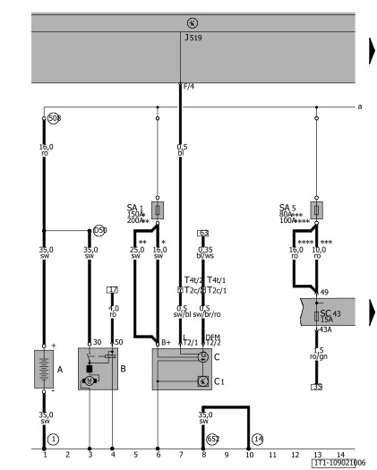
Dash panel insert, data bus diagnostic interface, self-diagnosis connection, electric power control fault lamp, multifunction display
J285 -   Control unit in dash panel insertK00589750804#BTJ285
J519 -   Onboard supply control unitK00589750804#BTJ519
J533 -   Data bus diagnostic interface, on left under dash panel, above relay carrierK00589750804#BTJ533
J119 -   Multifunction display
K132 -   Electric power control fault lamp
T16 -   16-pin connector, under dash panel left behind storage compartment, self-diagnosis connection
T20 -   20-pin connector
T36 -   36-pin connector
   44 -   Earth point, lower part of left A-pillarK00589750801#VB44
   367 -   Earth connection 2, in main wiring harness
   368 -   Earth connection 3, in main wiring harness
   605 -   Earth point, on top end of steering columnK00589750801#VB605
   A204 -   Connection (dash panel insert CAN bus, high), in dash panel wiring harness
   A205 -   Connection (dash panel insert CAN bus, low), in dash panel wiring harness
   B383 -   Connection 1 (drive train CAN bus, high), in main wiring harness
   B390 -   Connection 1 (drive train CAN bus, low), in main wiring harness
   B397 -   Connection 1 (convenience CAN bus, high), in main wiring harness
   B406 -   Connection 1 (convenience CAN bus, low), in main wiring harness
-●●- -   only for models with flexible service interval display

Touran Current Flow Diagram No.  109 / 18
https://portal-diagnostov.com/license.html
https://portal-diagnostov.com/license.html Automotive Electricians Portal FZCO Automotive Electricians Portal FZCO
Get access to all wiring diagrams of the carDownload PDF file
ws = white
sw = black
ro = red
rt = red
br = brown
gn = green
bl = blue
gr = grey
li = purple
vi = purple
ge = yellow
or = orange
rs = pink


Oil level and oil temperature sender, exhaust emissions warning lamp, fuel gauge sender, coolant temperature gauge, oil pressure switch, oil pressure warning lamp
F1 -   Oil pressure switch
G1 -   Fuel gauge
G3 -   Coolant temperature gauge
G32 -   Coolant shortage indicator sender
G266 -   Oil level and oil temperature sender
H3 -   Warning buzzer
J285 -   Control unit in dash panel insertK00589750804#BTJ285
J519 -   Onboard supply control unitK00589750804#BTJ519
K3 -   Oil pressure warning lamp
K31 -   Cruise control system warning lamp
K38 -   Oil level warning lamp (models with flexible service interval display only)
K83 -   Exhaust emissions warning lamp
K105 -   Reserve fuel warning lamp
T6z -   6-pin connector, near left headlightK00589750806#BTT6z
T14a -   14-pin connector, near batteryK00589750806#BTT14a
T36 -   36-pin connector
   410 -   Earth connection 1 (sender earth), in main wiring harness
-●●- -   only for models with flexible service interval display