| Golf Variant |
Current Flow Diagram |
No.
106 /
1
|
|
Wiring diagrams Volks Wagen
1.9l diesel engine , BLS
From February 2008
| Golf Variant |
Current Flow Diagram |
No.
106 /
2 |
|
 |
|
ws |
= |
white |
|
sw |
= |
black |
|
ro |
= |
red |
|
rt |
= |
red |
|
br |
= |
brown |
|
gn |
= |
green |
|
bl |
= |
blue |
|
gr |
= |
grey |
|
li |
= |
purple |
|
vi |
= |
purple |
|
ge |
= |
yellow |
|
or |
= |
orange |
|
rs |
= |
pink |
| |
| |
| |
| |
| |
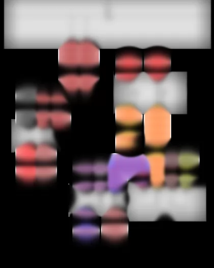
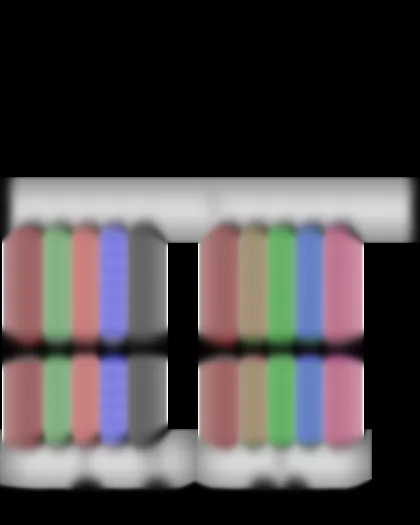
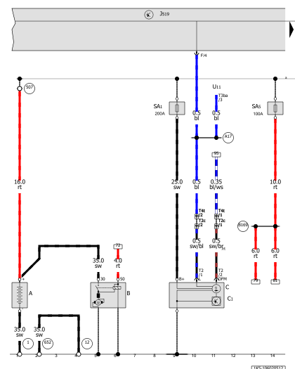
| Battery, Starter, Alternator, Onboard supply control unit
| J519 |
-
|
Onboard supply control unit |
| SA1 |
-
|
Fuse 1 in fuse holder A |
| SA5 |
-
|
Fuse 5 in fuse holder A |
| T4t |
-
|
4-pin connector, near starter |
| U11 |
-
|
Interior socket, 230 V, 110 V |
| 1 |
-
|
Earth strap, battery - body |
| 12 |
-
|
Earth point, on left in engine compartment |
| 507 |
-
|
Threaded connection (30), on battery fuse holder |
| 652 |
-
|
Earth point, engine and gearbox earth |
| A17 |
-
|
Connection (61), in dash panel wiring harness |
| B169 |
-
|
Positive connection 1 (30), in interior wiring harness |
|
| Golf Variant |
Current Flow Diagram |
No.
106 /
3 |
|
|
|
ws |
= |
white |
|
sw |
= |
black |
|
ro |
= |
red |
|
rt |
= |
red |
|
br |
= |
brown |
|
gn |
= |
green |
|
bl |
= |
blue |
|
gr |
= |
grey |
|
li |
= |
purple |
|
vi |
= |
purple |
|
ge |
= |
yellow |
|
or |
= |
orange |
|
rs |
= |
pink |
| |
| |
| |
| |
| |
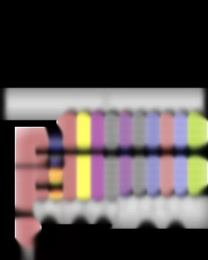
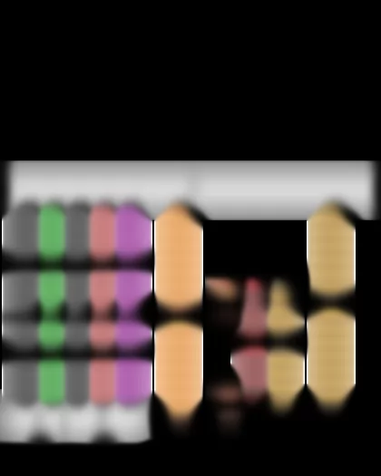
| Ignition/starter switch, Cruise control system switch, Cruise control system (CCS) SET button, Onboard supply control unit, Steering column electronics control unit
| D |
-
|
Ignition/starter switch |
| E45 |
-
|
Cruise control system switch |
| E227 |
-
|
Cruise control system (CCS) SET button |
| F319 |
-
|
Selector lever locked in position P switch |
| J519 |
-
|
Onboard supply control unit |
| J527 |
-
|
Steering column electronics control unit |
| J743 |
-
|
Mechatronic unit for dual clutch gearbox |
| * |
-
|
Only models with dual clutch gearbox 02E |
|
| Golf Variant |
Current Flow Diagram |
No.
106 /
4 |
|
| Golf Variant |
Current Flow Diagram |
No.
106 /
5 |
|
| Golf Variant |
Current Flow Diagram |
No.
106 /
6 |
|
|
|
ws |
= |
white |
|
sw |
= |
black |
|
ro |
= |
red |
|
rt |
= |
red |
|
br |
= |
brown |
|
gn |
= |
green |
|
bl |
= |
blue |
|
gr |
= |
grey |
|
li |
= |
purple |
|
vi |
= |
purple |
|
ge |
= |
yellow |
|
or |
= |
orange |
|
rs |
= |
pink |
| |
| |
| |
| |
| |
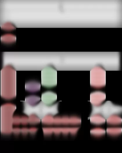
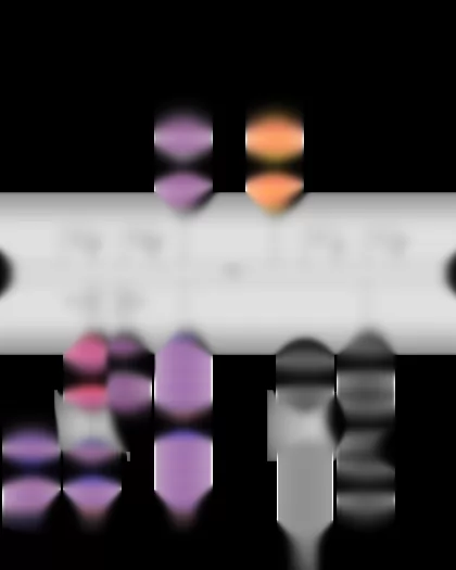
| Automatic glow period control unit, Glow plug 1, Glow plug 2, Glow plug 3, Glow plug 4
| J179 |
-
|
Automatic glow period control unit |
|
| Golf Variant |
Current Flow Diagram |
No.
106 /
7 |
|
|
|
ws |
= |
white |
|
sw |
= |
black |
|
ro |
= |
red |
|
rt |
= |
red |
|
br |
= |
brown |
|
gn |
= |
green |
|
bl |
= |
blue |
|
gr |
= |
grey |
|
li |
= |
purple |
|
vi |
= |
purple |
|
ge |
= |
yellow |
|
or |
= |
orange |
|
rs |
= |
pink |
| |
| |
| |
| |
| |
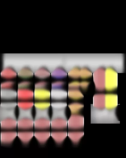
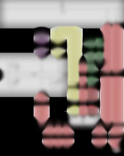
| Fuel gauge sender, Fuel system pressurisation pump, Fuel pump relay, Onboard supply control unit, Terminal 50 voltage supply relay
| G6 |
-
|
Fuel system pressurisation pump |
| J386 |
-
|
Driver door control unit |
| J519 |
-
|
Onboard supply control unit |
| J682 |
-
|
Terminal 50 voltage supply relay |
| SC12 |
-
|
Fuse 12 on fuse holder C |
| SC27 |
-
|
Fuse 27 on fuse holder C |
| A41 |
-
|
Positive connection (50), in dash panel wiring harness |
|
| Golf Variant |
Current Flow Diagram |
No.
106 /
8 |
|
|
|
ws |
= |
white |
|
sw |
= |
black |
|
ro |
= |
red |
|
rt |
= |
red |
|
br |
= |
brown |
|
gn |
= |
green |
|
bl |
= |
blue |
|
gr |
= |
grey |
|
li |
= |
purple |
|
vi |
= |
purple |
|
ge |
= |
yellow |
|
or |
= |
orange |
|
rs |
= |
pink |
| |
| |
| |
| |
| |
| Engine control unit
| J623 |
-
|
Engine control unit |
| 78 |
-
|
Earth point, lower part of right B-pillar |
| 131 |
-
|
Earth connection 2, in engine compartment wiring harness |
| 383 |
-
|
Earth connection 18, in main wiring harness |
| 607 |
-
|
Earth point, on left in plenum chamber |
| D182 |
-
|
Connection 3 (87a) in engine compartment wiring harness |
|
| Golf Variant |
Current Flow Diagram |
No.
106 /
9 |
|
|
|
ws |
= |
white |
|
sw |
= |
black |
|
ro |
= |
red |
|
rt |
= |
red |
|
br |
= |
brown |
|
gn |
= |
green |
|
bl |
= |
blue |
|
gr |
= |
grey |
|
li |
= |
purple |
|
vi |
= |
purple |
|
ge |
= |
yellow |
|
or |
= |
orange |
|
rs |
= |
pink |
| |
| |
| |
| |
| |
| Charge pressure sender, Intake air temperature sender, Accelerator position sender, Accelerator position sender 2, Engine control unit, Heater element for crankcase breather
| G31 |
-
|
Charge pressure sender |
| G42 |
-
|
Intake air temperature sender |
| G79 |
-
|
Accelerator position sender |
| G185 |
-
|
Accelerator position sender 2 |
| J623 |
-
|
Engine control unit |
| N79 |
-
|
Heater element for crankcase breather |
| 642 |
-
|
Earth point for electronically controlled fan |
| * |
-
|
Only models with crankcase breather heater element |
|
| Golf Variant |
Current Flow Diagram |
No.
106 /
10 |
|
|
|
ws |
= |
white |
|
sw |
= |
black |
|
ro |
= |
red |
|
rt |
= |
red |
|
br |
= |
brown |
|
gn |
= |
green |
|
bl |
= |
blue |
|
gr |
= |
grey |
|
li |
= |
purple |
|
vi |
= |
purple |
|
ge |
= |
yellow |
|
or |
= |
orange |
|
rs |
= |
pink |
| |
| |
| |
| |
| |
| Engine speed sender, Hall sender, Coolant temperature sender, Fuel temperature sender, Engine control unit
| G28 |
-
|
Engine speed sender |
| G62 |
-
|
Coolant temperature sender |
| G81 |
-
|
Fuel temperature sender |
| J623 |
-
|
Engine control unit |
|
| Golf Variant |
Current Flow Diagram |
No.
106 /
11 |
|
|
|
ws |
= |
white |
|
sw |
= |
black |
|
ro |
= |
red |
|
rt |
= |
red |
|
br |
= |
brown |
|
gn |
= |
green |
|
bl |
= |
blue |
|
gr |
= |
grey |
|
li |
= |
purple |
|
vi |
= |
purple |
|
ge |
= |
yellow |
|
or |
= |
orange |
|
rs |
= |
pink |
| |
| |
| |
| |
| |
| Radiator outlet coolant temperature sender, Engine control unit, Unit injector valve, No. 1 cyl., Unit injector valve, No. 2 cyl., Unit injector valve, No. 3 cyl., Unit injector valve, No. 4 cyl.
| G83 |
-
|
Radiator outlet coolant temperature sender |
| J623 |
-
|
Engine control unit |
| N240 |
-
|
Unit injector valve, No. 1 cyl. |
| N241 |
-
|
Unit injector valve, No. 2 cyl. |
| N242 |
-
|
Unit injector valve, No. 3 cyl. |
| N243 |
-
|
Unit injector valve, No. 4 cyl. |
| D140 |
-
|
Connection (injectors), in engine prewiring harness |
| E48 |
-
|
Connection (injectors), in injection system wiring harness |
|
| Golf Variant |
Current Flow Diagram |
No.
106 /
12 |
|
|
|
ws |
= |
white |
|
sw |
= |
black |
|
ro |
= |
red |
|
rt |
= |
red |
|
br |
= |
brown |
|
gn |
= |
green |
|
bl |
= |
blue |
|
gr |
= |
grey |
|
li |
= |
purple |
|
vi |
= |
purple |
|
ge |
= |
yellow |
|
or |
= |
orange |
|
rs |
= |
pink |
| |
| |
| |
| |
| |
| Air mass meter, Engine control unit, Charge pressure control solenoid valve, Exhaust gas recirculation cooler changeover valve
| J623 |
-
|
Engine control unit |
| N75 |
-
|
Charge pressure control solenoid valve |
| N345 |
-
|
Exhaust gas recirculation cooler changeover valve |
| D102 |
-
|
Connection 2 in engine compartment wiring harness |
| * |
-
|
Radiator fan connection |
|
| Golf Variant |
Current Flow Diagram |
No.
106 /
13 |
|
|
|
ws |
= |
white |
|
sw |
= |
black |
|
ro |
= |
red |
|
rt |
= |
red |
|
br |
= |
brown |
|
gn |
= |
green |
|
bl |
= |
blue |
|
gr |
= |
grey |
|
li |
= |
purple |
|
vi |
= |
purple |
|
ge |
= |
yellow |
|
or |
= |
orange |
|
rs |
= |
pink |
| |
| |
| |
| |
| |
| Brake light switch, Brake pedal switch, Clutch position sender, Engine control unit
| G476 |
-
|
Clutch position sender |
| J519 |
-
|
Onboard supply control unit |
| J623 |
-
|
Engine control unit |
| 402 |
-
|
Earth connection (interior light), in interior wiring harness |
| B131 |
-
|
Connection (54), in interior wiring harness |
|
| Golf Variant |
Current Flow Diagram |
No.
106 /
14 |
|
|
|
ws |
= |
white |
|
sw |
= |
black |
|
ro |
= |
red |
|
rt |
= |
red |
|
br |
= |
brown |
|
gn |
= |
green |
|
bl |
= |
blue |
|
gr |
= |
grey |
|
li |
= |
purple |
|
vi |
= |
purple |
|
ge |
= |
yellow |
|
or |
= |
orange |
|
rs |
= |
pink |
| |
| |
| |
| |
| |
| Lambda probe, Exhaust gas temperature sender 1, Exhaust gas temperature sender 2, Engine control unit
| G235 |
-
|
Exhaust gas temperature sender 1 |
| G448 |
-
|
Exhaust gas temperature sender 2 |
| J623 |
-
|
Engine control unit |
|
| Golf Variant |
Current Flow Diagram |
No.
106 /
15 |
|
|
|
ws |
= |
white |
|
sw |
= |
black |
|
ro |
= |
red |
|
rt |
= |
red |
|
br |
= |
brown |
|
gn |
= |
green |
|
bl |
= |
blue |
|
gr |
= |
grey |
|
li |
= |
purple |
|
vi |
= |
purple |
|
ge |
= |
yellow |
|
or |
= |
orange |
|
rs |
= |
pink |
| |
| |
| |
| |
| |
| Exhaust gas recirculation potentiometer, Intake manifold flap potentiometer, Engine control unit, Exhaust gas recirculation valve, Intake manifold flap motor
| G212 |
-
|
Exhaust gas recirculation potentiometer |
| G336 |
-
|
Intake manifold flap potentiometer |
| J623 |
-
|
Engine control unit |
| N18 |
-
|
Exhaust gas recirculation valve |
| V157 |
-
|
Intake manifold flap motor |
|
| Golf Variant |
Current Flow Diagram |
No.
106 /
16 |
|
|
|
ws |
= |
white |
|
sw |
= |
black |
|
ro |
= |
red |
|
rt |
= |
red |
|
br |
= |
brown |
|
gn |
= |
green |
|
bl |
= |
blue |
|
gr |
= |
grey |
|
li |
= |
purple |
|
vi |
= |
purple |
|
ge |
= |
yellow |
|
or |
= |
orange |
|
rs |
= |
pink |
| |
| |
| |
| |
| |
| Exhaust gas pressure sensor 1, Temperature sender after particulate filter, Engine control unit
| G450 |
-
|
Exhaust gas pressure sensor 1 |
| G527 |
-
|
Temperature sender after particulate filter |
| J623 |
-
|
Engine control unit |
| B383 |
-
|
Connection 1 (powertrain CAN bus, high), in main wiring harness |
| B390 |
-
|
Connection 1 (powertrain CAN bus, low), in main wiring harness |
|
| Golf Variant |
Current Flow Diagram |
No.
106 /
17 |
|
|
|
ws |
= |
white |
|
sw |
= |
black |
|
ro |
= |
red |
|
rt |
= |
red |
|
br |
= |
brown |
|
gn |
= |
green |
|
bl |
= |
blue |
|
gr |
= |
grey |
|
li |
= |
purple |
|
vi |
= |
purple |
|
ge |
= |
yellow |
|
or |
= |
orange |
|
rs |
= |
pink |
| |
| |
| |
| |
| |
| Onboard supply control unit, Data bus diagnostic interface, Engine control unit
| J519 |
-
|
Onboard supply control unit |
| J533 |
-
|
Data bus diagnostic interface |
| J587 |
-
|
Selector lever sensors control unit |
| J623 |
-
|
Engine control unit |
| SC1 |
-
|
Fuse 1 on fuse holder C |
| SC2 |
-
|
Fuse 2 on fuse holder C |
| SC4 |
-
|
Fuse 4 on fuse holder C |
| A2 |
-
|
Positive connection (15), in dash panel wiring harness |
| A76 |
-
|
Connection (K-diagnosis wire), in dash panel wiring harness |
| A192 |
-
|
Positive connection 3 (15a) in dash panel wiring harness |
| A199 |
-
|
Positive connection 4 (15a) in dash panel wiring harness |
| B383 |
-
|
Connection 1 (powertrain CAN bus, high), in main wiring harness |
| B390 |
-
|
Connection 1 (powertrain CAN bus, low), in main wiring harness |
| B397 |
-
|
Connection 1 (convenience CAN bus, high), in main wiring harness |
| B406 |
-
|
Connection 1 (convenience CAN bus, low), in main wiring harness |
| * |
-
|
Only models with dual clutch gearbox 02E |
| *2 |
-
|
Only models with crankcase breather heater element |
|
| Golf Variant |
Current Flow Diagram |
No.
106 /
18 |
|
|
|
ws |
= |
white |
|
sw |
= |
black |
|
ro |
= |
red |
|
rt |
= |
red |
|
br |
= |
brown |
|
gn |
= |
green |
|
bl |
= |
blue |
|
gr |
= |
grey |
|
li |
= |
purple |
|
vi |
= |
purple |
|
ge |
= |
yellow |
|
or |
= |
orange |
|
rs |
= |
pink |
| |
| |
| |
| |
| |
| Rev. counter, Speedometer, Multifunction indicator, Control unit in dash panel insert, Data bus diagnostic interface
| J119 |
-
|
Multifunction indicator |
| J285 |
-
|
Control unit in dash panel insert |
| J533 |
-
|
Data bus diagnostic interface |
| K2 |
-
|
Alternator warning lamp |
| K29 |
-
|
Glow period warning lamp |
|
| Golf Variant |
Current Flow Diagram |
No.
106 /
19 |
|
|
|
ws |
= |
white |
|
sw |
= |
black |
|
ro |
= |
red |
|
rt |
= |
red |
|
br |
= |
brown |
|
gn |
= |
green |
|
bl |
= |
blue |
|
gr |
= |
grey |
|
li |
= |
purple |
|
vi |
= |
purple |
|
ge |
= |
yellow |
|
or |
= |
orange |
|
rs |
= |
pink |
| |
| |
| |
| |
| |
| Oil pressure switch, Fuel gauge, Coolant temperature gauge, Coolant shortage indicator sender, Buzzer and gong, Control unit in dash panel insert
| G3 |
-
|
Coolant temperature gauge |
| G32 |
-
|
Coolant shortage indicator sender |
| J285 |
-
|
Control unit in dash panel insert |
| K3 |
-
|
Oil pressure warning lamp |
| K28 |
-
|
Coolant temperature and coolant shortage warning lamp |
| K105 |
-
|
Reserve fuel warning lamp |
| 410 |
-
|
Earth connection 1 (sender earth) in main wiring harness |
|
| Golf Variant |
Current Flow Diagram |
No.
106 /
20 |
|
|
|
ws |
= |
white |
|
sw |
= |
black |
|
ro |
= |
red |
|
rt |
= |
red |
|
br |
= |
brown |
|
gn |
= |
green |
|
bl |
= |
blue |
|
gr |
= |
grey |
|
li |
= |
purple |
|
vi |
= |
purple |
|
ge |
= |
yellow |
|
or |
= |
orange |
|
rs |
= |
pink |
| |
| |
| |
| |
| |
| Oil level and oil temperature sender, Control unit in dash panel insert, Onboard supply control unit, Cruise control system warning lamp, Oil level warning lamp, Electronic power control fault lamp
| G65 |
-
|
High-pressure sender |
| G266 |
-
|
Oil level and oil temperature sender |
| J285 |
-
|
Control unit in dash panel insert |
| J519 |
-
|
Onboard supply control unit |
| K31 |
-
|
Cruise control system warning lamp |
| K38 |
-
|
Oil level warning lamp |
| K132 |
-
|
Electronic power control fault lamp |
| 367 |
-
|
Earth connection 2, in main wiring harness |
| 602 |
-
|
Earth point, in front left footwell |
| A20 |
-
|
Positive connection (15a), in dash panel wiring harness |
|
Can't find your car? Check -> DiagnostData.com!
 English