AIR CONDITIONING
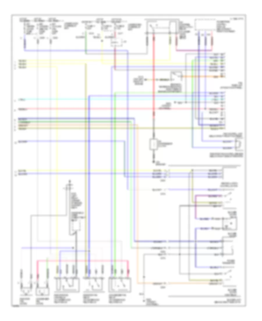
Automatic A/C-Heater System Wiring Diagram (Legend Wiring Diagram 1 Of 2) for Acura Legend GS 1994

List of elements for Automatic A/C-Heater System Wiring Diagram (Legend Wiring Diagram 1 Of 2) for Acura Legend GS 1994:
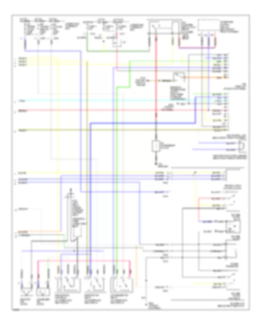
Automatic A/C-Heater System Wiring Diagram (Legend Wiring Diagram 2 Of 2) for Acura Legend GS 1994
List of elements for Automatic A/C-Heater System Wiring Diagram (Legend Wiring Diagram 2 Of 2) for Acura Legend GS 1994:
Manual A/C Wiring Diagram (1 of 2) for Acura Legend GS 1994
List of elements for Manual A/C Wiring Diagram (1 of 2) for Acura Legend GS 1994:
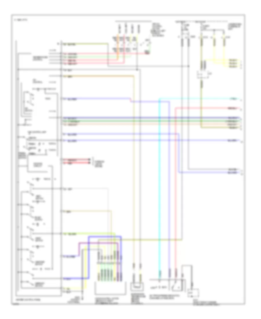
Manual A/C Wiring Diagram (2 of 2) for Acura Legend GS 1994
List of elements for Manual A/C Wiring Diagram (2 of 2) for Acura Legend GS 1994: