AIR CONDITIONING
Automatic A/C Wiring Diagram (1 of 2) for Audi 200 Quattro 1991

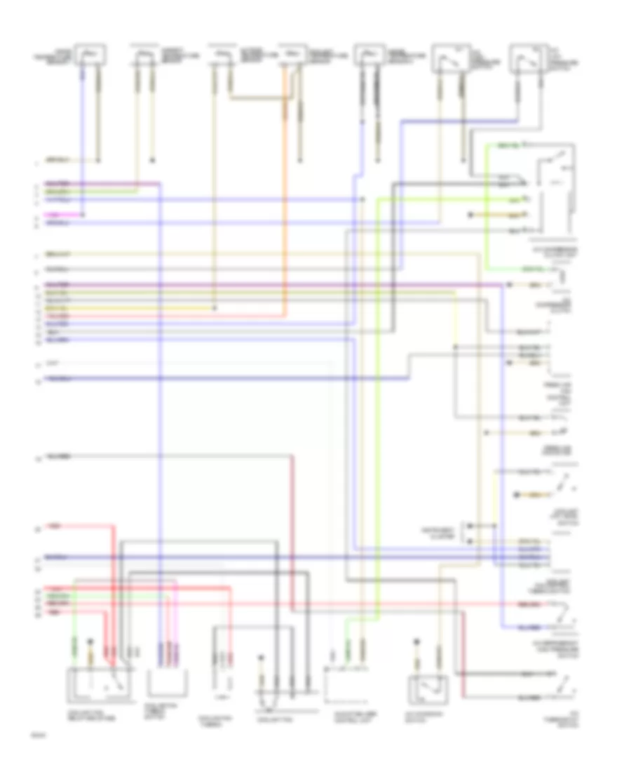
List of elements for Automatic A/C Wiring Diagram (1 of 2) for Audi 200 Quattro 1991:
- (not used)
- A/c control head
- A/c programmer
- Alternator
- Battery
- Control pressure regulator
- Coolant fan relay #2
- Coolant fan relay #3
- Coolant pump thermo switch
- Cooling fan after run control unit
- Fuse 15a
- Fuse 21 25a
- Fuse 25a
- Fuse 30a
- Fuse 5a
- Fuse/ relay panel
- Hot w/ lights on
- Hot w/ load reduction relay energized
- Ignition(15)
- Ignition(35)
- Injector coolant fan
- Injector coolant fan relay
- Instrument cluster
- Interior temperature sensor 1 fan
- Red
- Temp regulator flap motor
- Thermo switch
- Turbo coolant pump
Automatic A/C Wiring Diagram (2 of 2) for Audi 200 Quattro 1991
List of elements for Automatic A/C Wiring Diagram (2 of 2) for Audi 200 Quattro 1991:
- A/c
- A/c compressor clutch
- A/c compressor clutch unit
- A/c high pressure switch
- A/c kickdown switch
- A/c refrigerant high pressure switch
- A/c thermostat switch
- Ambient temperature sensor
- Control unit
- Coolant fan
- Coolant fan control thermo switch
- Coolant fan relay-3rd stage
- Coolant low level
- Coolant temperature sensor
- Cooling fan
- Cooling fan thermo switch
- Fan
- Fresh air
- Fresh air fan motor
- Idle stabilizer control unit
- Inside temperature sensor 1
- Inside temperature sensor 2
- Instrument cluster
- Low pressure switch
- Outside temperature sensor
- Red
- Switch
- Thermo