AIR CONDITIONING
Automatic A/C Wiring Diagram, Early Production (1 of 3) for Audi A3 2007

List of elements for Automatic A/C Wiring Diagram, Early Production (1 of 3) for Audi A3 2007:
- (behind right kick panel) g638
- (in right plenum chamber) air quality sensor
- 16a
- 22a
- 37a
- A/c compressor regulator valve
- Climatronic control module
- Evaporator vent temperature sensor (right front of center console)
- Fresh air blower control module (below right side of dash)
- Fresh air intake duct temperature sensor
- Fuse 10a
- Fuse 20a
- Fuse 40a
- Fuse 5a
- Fuse panel c
- G638 (behind right kick panel)
- High pressure sensor
- Hot at all times
- Left footwell vent temperature sensor
- Left temperature flap potentiometer/ actuator
- Red
- Right footwell vent temperature sensor
- Seats system
- T16d
- T20j
Automatic A/C Wiring Diagram, Early Production (2 of 3) for Audi A3 2007
List of elements for Automatic A/C Wiring Diagram, Early Production (2 of 3) for Audi A3 2007:
- (top left center of dash) sunlight photo sensor
- Air flow flap motor & position sensor
- Central flap motor & position sensor
- Climatronic control module
- Computer data lines system
- Defroster flap motor & position sensor
- Fuse 50a
- Fuse panel b (integrated in e-box high)
- Hot at all times
- Left vent temperature sensor
- Recirculation flap motor & position sensor (behind glove box)
- Red
- Right temperature flap potentiometer/ actuator
- Right vent temperature sensor
- Seats system
- T12f
- T16e
- T40
Automatic A/C Wiring Diagram, Early Production (3 of 3) for Audi A3 2007
List of elements for Automatic A/C Wiring Diagram, Early Production (3 of 3) for Audi A3 2007:
- 2.0l
- 2.0l 3.2l
- 3.2l
- After-run coolant pump (left side of engine, below oil filter)
- Coolant circulation pump relay
- Coolant fan 2
- Coolant fan control (fc) control module (front of engine compartment)
- E-box high
- Engine controls system
- Engine coolant temperature sensor (on radiator)
- Fuse 10a
- Fuse 50a
- Fuse 5a
- Fuse panel a
- Fuse panel b
- G607 (in left plenum chamber)
- G673 (on left front long member)
- Hot at all times
- Motronic engine control module (ecm) (in center of plenum chamber)
- Nca
- T121
- T26
- T2e
- T40
- T4d
- T94
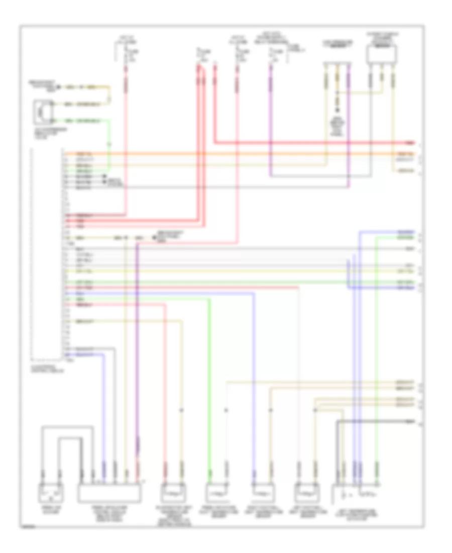
Automatic A/C Wiring Diagram, Late Production (1 of 3) for Audi A3 2007
List of elements for Automatic A/C Wiring Diagram, Late Production (1 of 3) for Audi A3 2007:
- (behind right kick panel) g638
- (in right plenum chamber) air quality sensor
- 16a
- 22a
- 37a
- A/c compressor regulator valve
- Climatronic control module
- Evaporator vent temperature sensor (right front of center console)
- Fresh air blower
- Fresh air blower control module (below right side of dash)
- Fresh air intake duct temperature sensor
- Fuse 10a
- Fuse 20a
- Fuse 40a
- Fuse 5a
- Fuse panel c
- G638 (behind right kick panel)
- High pressure sensor
- Hot at all times
- Left footwell vent temperature sensor
- Left temperature flap potentiometer/ actuator
- Nca
- Red
- Right footwell vent temperature sensor
- Seats system
- T16d
- T20j
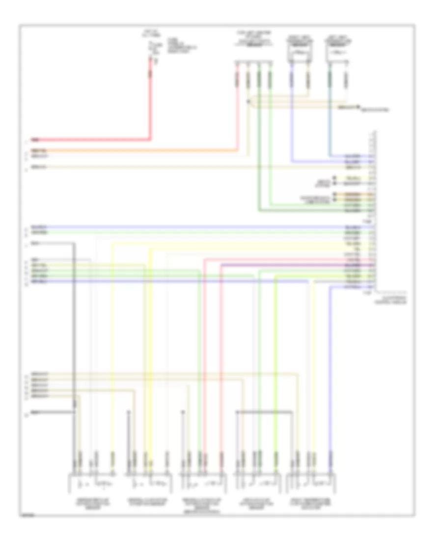
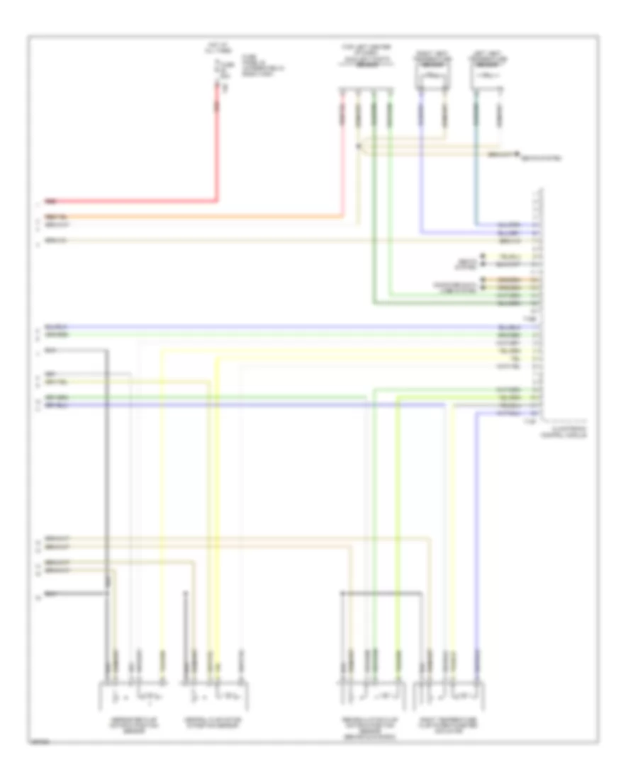
Automatic A/C Wiring Diagram, Late Production (2 of 3) for Audi A3 2007
List of elements for Automatic A/C Wiring Diagram, Late Production (2 of 3) for Audi A3 2007:
- (top left center of dash) sunlight photo sensor
- Central flap motor & position sensor
- Climatronic control module
- Computer data lines system
- Defroster flap motor & position sensor
- Fuse 50a
- Fuse panel b (integrated in e-box high)
- Hot at all times
- Left vent temperature sensor
- Recirculation flap motor & position sensor (behind glove box)
- Red
- Right temperature flap potentiometer/ actuator
- Right vent temperature sensor
- Seats system
- T12f
- T16e
- T40
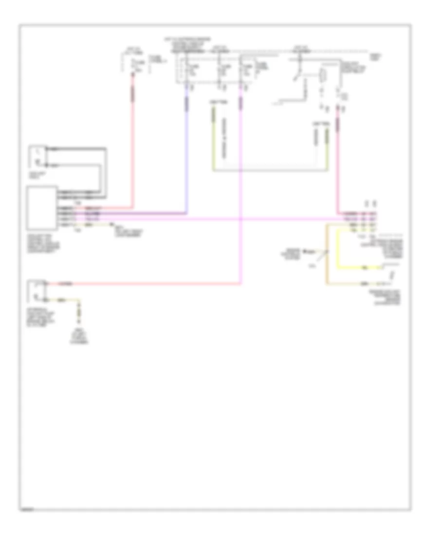
Automatic A/C Wiring Diagram, Late Production (3 of 3) for Audi A3 2007
List of elements for Automatic A/C Wiring Diagram, Late Production (3 of 3) for Audi A3 2007:
- 2.0l
- 2.0l 3.2l
- 3.2l
- After-run coolant pump (left side of engine, below oil filter)
- Coolant circulation pump relay
- Coolant fan 2
- Coolant fan control (fc) control module (front of engine compartment)
- E-box high
- Engine controls system
- Engine coolant temperature sensor (on radiator)
- Fuse 10a
- Fuse 50a
- Fuse 5a
- Fuse panel a
- Fuse panel b
- G607 (in left plenum chamber)
- G673 (on left front long member)
- Hot at all times
- Motronic engine control module (ecm) (in center of plenum chamber)
- Nca
- T121
- T26
- T2e
- T40
- T4d
- T94