AIR CONDITIONING
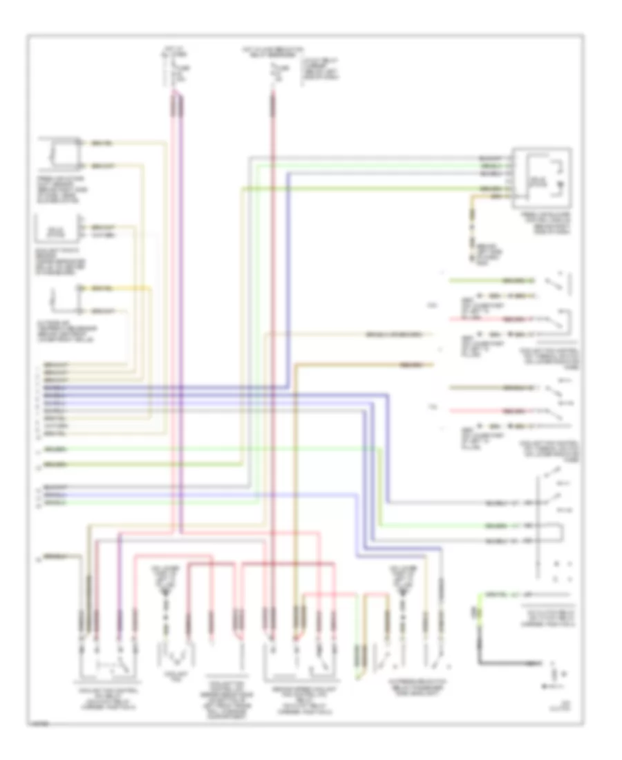
Automatic A/C Wiring Diagram (1 of 2) for Audi A4 Quattro 2001

List of elements for Automatic A/C Wiring Diagram (1 of 2) for Audi A4 Quattro 2001:
- A/c control head
- A10
- A11
- A12
- B10
- B11
- B12
- B13
- B14
- B15
- B16
- B17
- B18
- B19
- B20
- Back pressure flap motor position sensor (behind right side of dash, near base of "a"pillar)
- C10
- C11
- C12
- C13
- C14
- C15
- C16
- Center outlet temperature sender (behind lower center of dash, on hvac unit)
- Central flap motor position sensor (behind lower right center of dash, on hvac unit)
- D10
- D11
- D12
- D13
- D14
- D15
- D16
- Floor outlet temperature sender (behind lower left center of dash, on hvac unit)
- Footwell/defrost flap motor position sensor (behind lower center of dash, above accelerator pedal)
- Fuse 10a
- Fuse 30a
- Fuse 5a
- Fuse panel (on left end of dash)
- G202 (behind left side of dash)
- Hot in run or start
- Hot w/light switch in park or head position
- Hot w/load reduction relay energized
- Instrument cluster
- Motronic engine control module (ecm) (near brake booster, in protective case)
- Solid state
- T32
- T32a
- Temperature flap motor position sensor (behind lower right center of dash, near transmission tunnel)
- Wiper/washer system
Automatic A/C Wiring Diagram (2 of 2) for Audi A4 Quattro 2001
List of elements for Automatic A/C Wiring Diagram (2 of 2) for Audi A4 Quattro 2001:
- (behind left side of dash) g202
- (on lower part of left "a" pillar) g900
- 1.8l
- 2.8l
- 8-way relay carrier (below left end of dash)
- A/c clutch
- A/c clutch relay (on 13 way relay carrier, position 3)
- A/c pressure switch (below passenger side headlight)
- Coolant fan
- Coolant fan control (fc) relay (on 8-way relay carrier, position 3)
- Coolant fan control (fc) series resistance (on bottom of left front frame rail, in engine compartment)
- Coolant fan control (fc) thermal switch (on lower radiator hose)
- Fresh air blower control module (behind right side of dash)
- Fresh air intake duct sensor (behind right side of dash, near blower motor)
- Fuse 40a
- Fuse 5a
- G900 (on lower part of left "a" pillar)
- Hot at all times
- Hot w/load reduction relay energized
- Nca
- Outside air temperature sensor (behind center of lower front grille)
- Second speed coolant fan control (fc) relay (on 8-way relay carrier, position 2)
- Solid state
- Sunlight photo sensor (inside defroster grille, on center of dashboard)