AIR CONDITIONING
Automatic A/C Wiring Diagram (1 of 3) for Audi A8 L Quattro 2001

List of elements for Automatic A/C Wiring Diagram (1 of 3) for Audi A8 L Quattro 2001:
- (behind lower left center of dash, on hvac assembly)
- (behind lower left center of dash, on hvac assembly) left footwell flap motor/position sensor
- (behind lower right center of dash, on hvac assembly) right footwell flap motor/position sensor
- (behind right center of dash, on hvac assembly) flap motor temperature regulator/position sensor
- (left rear of engine compt)
- (left rear of engine compt) recirculation flap motor/ position sensor
- 1/+
- 2/-
- A/c control head
- A10
- A11
- A12
- A13
- A14
- A15
- A16
- A17
- A18
- A19
- A20
- A21
- A22
- A23
- A24
- Air flow flap motor/ back pressure flap motor position sensor
- B10
- B11
- B12
- B13
- B14
- B15
- B16
- B17
- B18
- B19
- B20
- B21
- B22
- Center vent adjusting motor/position sensor
- Fresh air blower (center rear of engine compt)
- Fresh air blower control module (right rear of engine compt)
- G43 (above right kick panel)
- Interior monitoring sensors control module
- Left center vent motor/position sensor (behind upper left center of dash, on hvac assembly)
- Rear footwell vent motor/position sensor (behind lower left center of dash, on hvac assembly)
- Red
- Right center vent motor/position sensor (behind upper right center of dash, on hvac assembly)
- Solid state
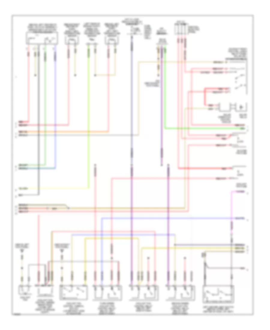
Automatic A/C Wiring Diagram (2 of 3) for Audi A8 L Quattro 2001
List of elements for Automatic A/C Wiring Diagram (2 of 3) for Audi A8 L Quattro 2001:
- (above left kick panel) g44
- (above right kick panel) g43
- (behind left center of dash) left vent temperature sensor
- (behind left center of dash, on hvac assembly) defroster flap motor/ position sensor
- (behind right center of dash) right vent temperature sensor
- (left rear of engine compt) fresh air intake duct temperature sensor
- (on right front footwell e-box relay panel) solar cell separation relay
- (or red)
- 40a
- 60a
- Air quality sensor
- Blower fan fuse
- Central electric panel
- Coolant fan
- Coolant fan control relay (below left side of dash)
- Coolant fan control series resistance (lower left front of engine compt)
- Coolant fan control thermal switch (lower right side of radiator)
- Coolant fan fuse
- Fuse 4 (st2) 5a
- Fuse panel (right front foot- well)
- G43 (above right kick panel)
- Hot at all times
- Hot w/ load reduction relay energized
- Left center vent switch (behind upper left center of dash, on vent)
- Nca
- Red
- Second speed coolant fan control relay (below left side of dash)
- Solar cells
- Solar operation control module
- Solid state
- Third speed coolant fan control relay (below left side of dash)
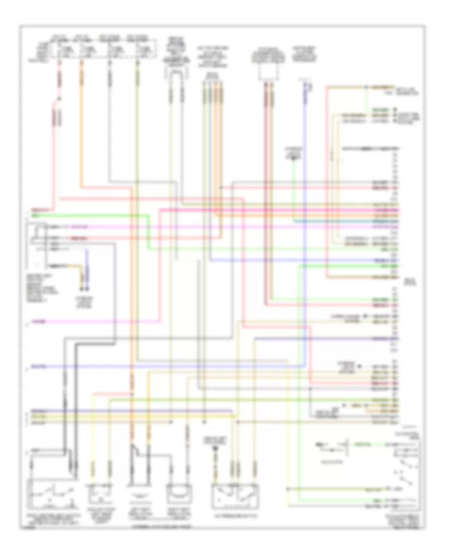
Automatic A/C Wiring Diagram (3 of 3) for Audi A8 L Quattro 2001
List of elements for Automatic A/C Wiring Diagram (3 of 3) for Audi A8 L Quattro 2001:
- (2000)
- (above left kick panel) g43
- (behind center of lower radiator grill) outside air temperature sensor
- (in plenum chamber e-box) motronic engine control module
- (integral with coolant pump)
- (on top center
- 1/+
- 2/-
- A/c clutch
- A/c clutch relay (on right front footwell e-box relay panel)
- A/c control head
- A/c pressure switch
- C10
- C11
- C12
- C13
- C14
- C15
- C16
- C17
- C18
- C19
- C20
- C21
- C22
- C23
- C24
- Center vent position sensor (behind upper center of dash, on hvac assembly)
- Computer data lines system
- Coolant pump (left rear of engine compt)
- D10
- D11
- D12
- E10
- E11
- E12
- Fuse 4 (st3) 10a
- Fuse 5 (st3) 10a
- Fuse 7 (st3) 15a
- Fuse 8 (st3) 10a
- Fuse panel (right front footwell)
- G43 (above left kick panel)
- Hot at all times
- Hot in run and start
- Instrument cluster combination processor
- Interior lights system
- Left heat regulating valve
- Nca
- Of middle defrost vent) sunlight photo sensor
- Right center vent switch (behind upper right center of dash, on vent)
- Right heat regulating valve
- Solid state
- T16a
- T32b
- Wiper/washer system