AIR CONDITIONING
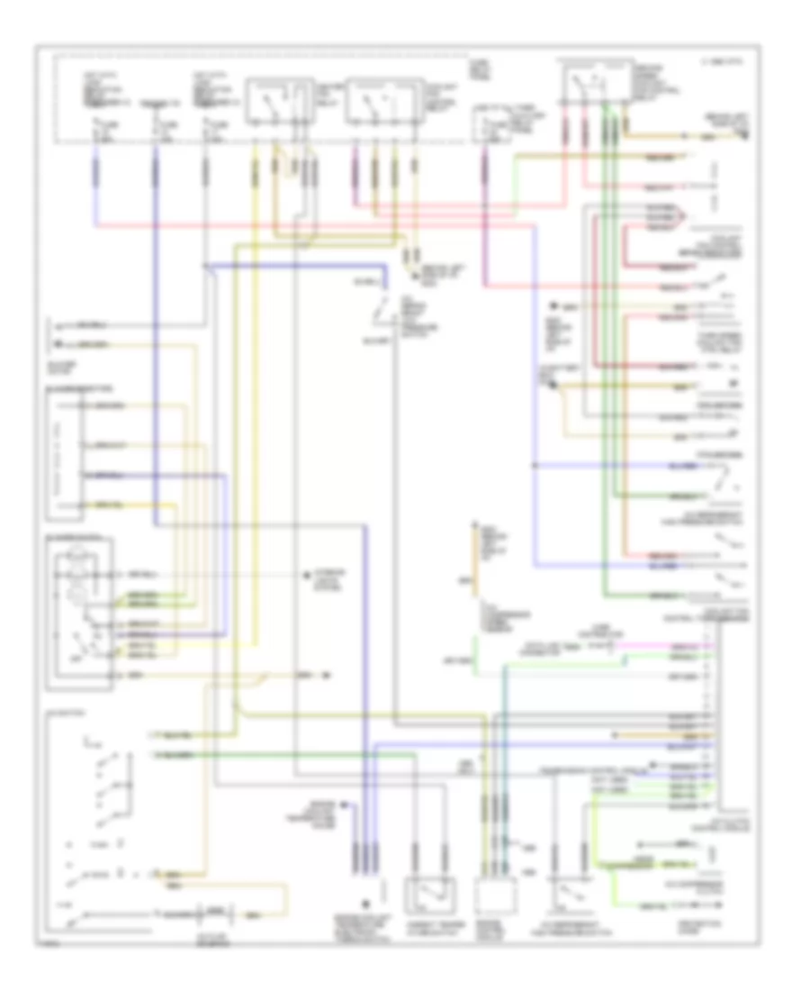
Manual A/C Wiring Diagram for Audi Cabriolet 1996
List of elements for Manual A/C Wiring Diagram for Audi Cabriolet 1996:
- (behind left side of i/p) g202
- (in battery box) g100
- (near compressor)
- (not used)
- 1995 vftc c
- A/c clutch control module
- A/c compressor clutch
- A/c compressor speed sensor
- A/c flap solenoid
- A/c refrig- erant low pressure switch
- A/c refrigerant
- A/c refrigerant high pressure switch
- A/c switch
- Ambient temper- ature switch
- Auxiliary relay panel
- B10
- Blower motor
- Blower resistors
- Blower switch
- C10
- C11
- Coolant fan
- Coolant fan control relay
- Coolant fan control series resistors
- Coolant fan control thermoswitch
- Data link connector
- Engine control module
- Engine coolant temperature electronic thermo switch
- Engine coolant temperature gauge
- Fuse 15a
- Fuse 25a
- Fuse 30a
- Fuse 60a
- Fuse/ relay panel
- G202 (behind left side of i/p)
- Heater fan
- High pressure switch
- Hot at all times
- Hot with load reduction relay energized (x)
- Ignition (15)
- Interior lights system
- Off
- Only
- Protection diode
- Relay
- Second speed coolant fan control relay
- Third speed coolant fan ctrl relay
- Transmission control module
- Wire distributor
 English