AIR CONDITIONING
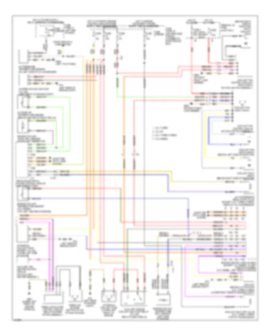
Automatic A/C Wiring Diagram, Basic (1 of 2) for Audi Q5 TDI Prestige 2014

List of elements for Automatic A/C Wiring Diagram, Basic (1 of 2) for Audi Q5 TDI Prestige 2014:
- (left rear of engine compt) g12
- (under left front of center console) g687
- 10a
- 13a
- 17a
- 2.0l turbo
- 2.0l turbo hybrid
- Air flow door motor (left side of air intake housing)
- Center vent adjustment motor (right side of hvac unit)
- Center vent temperature sensor
- Climatronic control module
- Climatronic refrigerant shut-off valve (except 3.0l sc) (rear center of engine compt)
- Compressor magnetic clutch (2.0l turbo)
- Computer data
- Computer data lines system
- Coolant recirculation pump (except 2.0l turbo hybrid) (lower right rear of engine compt)
- Defroster door motor (left side of hvac unit)
- Electric drive power & control electronics (right plenum chamber)
- Electrical a/c compressor
- Electrical a/c compressor control module (on a/c compressor)
- Evaporator vent temperature sensor (right side of evaporator housing)
- Footwell door motor (left side of hvac unit)
- Footwell vent temperature sensor
- Fuse 10a
- Fuse 40a
- Fuse 5a
- Fuse carrier
- Fuse panel b (driver's side plenum chamber on electronics box)
- Fuse panel d (right end of dash)
- G12 (left rear of engine compt)
- Hot at all times
- Lines system
- Low temperature circuit coolant pump (2.0l turbo hybrid)
- Nca
- Recirculation door motor (left side of air intake housing)
- Red
- Sunlight photo sensor (top center of dash)
- T16i
- T17b
- T17e
- T17q
- T20e
- T28jx
- T4jx
- Temperature regulator door motor
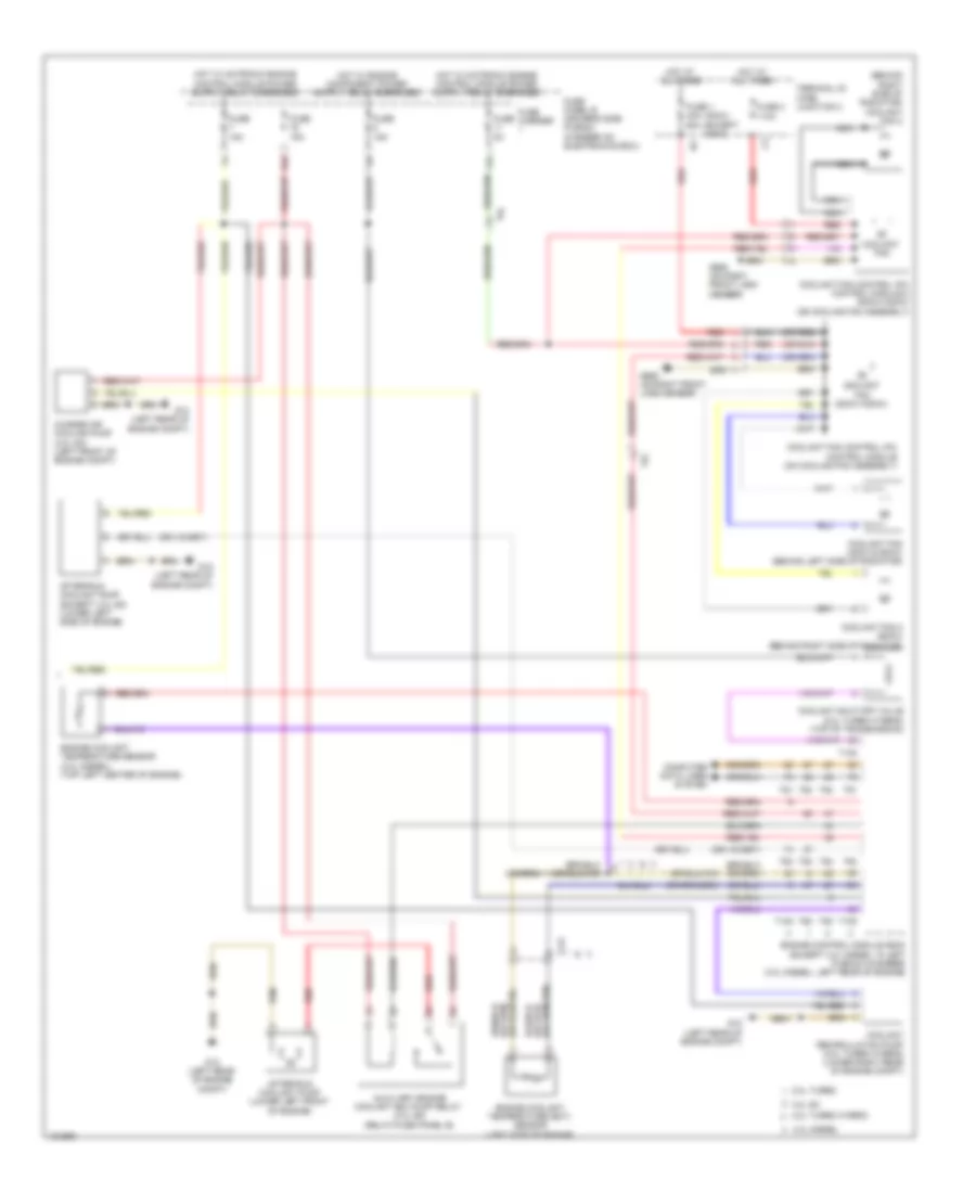
Automatic A/C Wiring Diagram, Basic (2 of 2) for Audi Q5 TDI Prestige 2014
List of elements for Automatic A/C Wiring Diagram, Basic (2 of 2) for Audi Q5 TDI Prestige 2014:
- (400w) (except 400w)
- (behind right side of radiator) (800w) coolant fan 2
- (or red)
- 11a
- 16a
- 2.0l turbo
- 2.0l turbo hybrid
- 3.0l diesel
- 3.0l sc
- A/c compressor regulator valve (except 2.0l turbo hybrid) (rear of a/c compressor)
- A/c pressure/ temperature sensor (on left side of a/c condenser)
- After-run coolant pump (except 3.0l sc) (lower left side of engine)
- After-run coolant pump (lower left front of engine)
- Auxiliary air heater control module (on auxiliary heater assembly)
- Auxiliary engine coolant (ec) pump relay (3.0l sc) (relay/fuse panel b)
- Charge air cooling pump (3.0l sc) (left front of engine compt)
- Computer data lines system
- Coolant fan (400w & 600w) (behind left side of radiator)
- Coolant fan (800w/1000w)
- Coolant fan 2 (600w) (behind right side of radiator)
- Coolant fan control module (on cooling fan assembly)
- Coolant fan control module 2 (800w/1000w) (on cooling fan assembly)
- Coolant recirculation pump (2.0l turbo hybrid) (lower right rear of engine compt)
- Coolant shut-off valve (2.0l turbo hybrid) (top of transmission)
- Engine control module (ecm) (except 3.0l diesel: in left plenum chamber) (3.0l diesel: left rear of engine)
- Engine coolant level (ecl) sensor (in coolant reservoir)
- Engine coolant temperature (ect) sensor (left side of engine)
- Engine coolant temperature sensor (3.0l diesel) (top left center of engine)
- Fresh air blower (bottom of air intake housing)
- Fresh air blower control module (below blower motor assembly)
- Fuse 1 40a 60a
- Fuse 110a
- Fuse 15a
- Fuse 5a
- Fuse carrier
- Fuse panel b (driver's side plenum chamber on electronics box)
- Fuse panel c (left end of dash)
- G12 (left rear of engine compt)
- G639 (left kick panel)
- G685 (on right front long member)
- G687 (under left front of center console)
- Hot at all times
- Nca
- Outside air temperature sensor (behind center of front grille)
- Red
- T105
- T14f
- T16b
- T17i
- T17r
- T32b
- T5l
- T60
- T91
- T94
- Terminal 30 wire junction 2
- Vehicle electrical system control module (left side of dash)
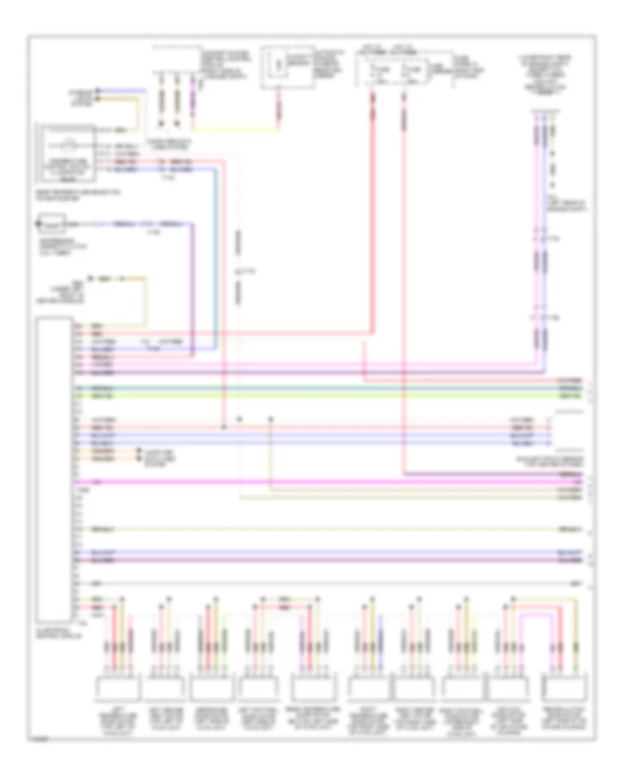
Automatic A/C Wiring Diagram, Comfort (1 of 3) for Audi Q5 TDI Prestige 2014
List of elements for Automatic A/C Wiring Diagram, Comfort (1 of 3) for Audi Q5 TDI Prestige 2014:
- (lower right rear of engine compt) (except 2.0l turbo hybrid) coolant recirculation pump
- 10a
- Air flow door motor (left side of air intake housing)
- Automatic dimming interior rearview mirror
- Climatronic control module
- Comfort system central control module (right side of luggage compt) t32c
- Compressor magnetic clutch (2.0l turbo)
- Computer data lines system
- Defroster door motor (left side of hvac unit)
- Fuse 10a
- Fuse 40a
- Fuse carrier
- Fuse panel d (right end of dash)
- G12 (left rear of engine compt)
- G687 (under left front of center console)
- Hot at all times
- Humidity sensor
- Interior lights system
- Left center vent motor (top left of hvac unit)
- Left footwell door motor (left side of hvac unit)
- Left temperature door motor (top left of hvac unit)
- Nca
- Rear temperature door motor (bottom left side of hvac unit)
- Rear temperature selection potentiometer
- Recirculation door motor (left side of air intake housing)
- Red
- Right center vent motor (top right side of hvac unit)
- Right footwell door motor (lower right side of hvac unit)
- Right temperature door motor (top right side of hvac unit)
- Sunlight photo sensor (top center of dash)
- T16i
- T17b
- T17d
- T17q
- T20e
- Temperature control switch illumination bulb
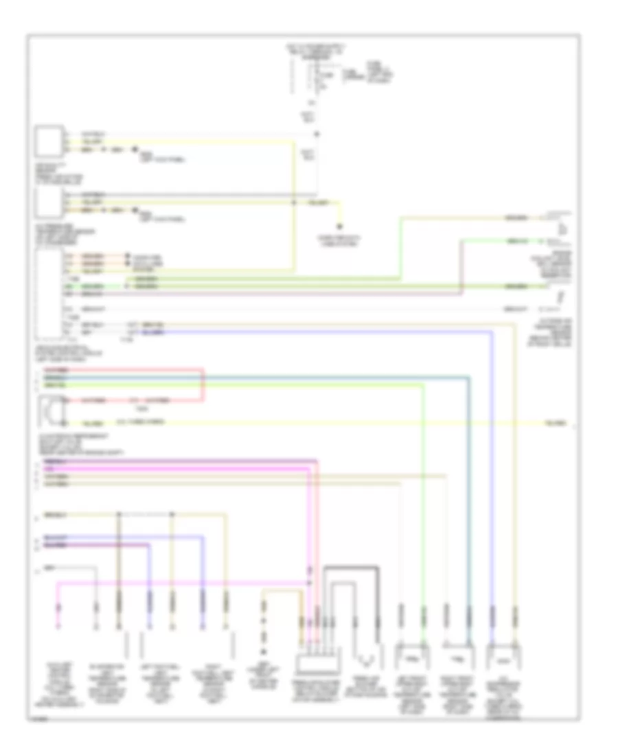
Automatic A/C Wiring Diagram, Comfort (2 of 3) for Audi Q5 TDI Prestige 2014
List of elements for Automatic A/C Wiring Diagram, Comfort (2 of 3) for Audi Q5 TDI Prestige 2014:
- 2.0l turbo hybrid
- A/c compressor regulator valve (except 2.0l turbo hybrid) (rear of a/c compressor)
- A/c pressure/ temperature sensor (on left side of a/c condenser)
- Air quality sensor (fresh air intake w/ intake grille)
- Auxiliary heater control module (2.0l turbo hybrid) (on auxiliary heater assembly)
- Climatronic refrigerant shut-off valve (except 3.0l sc) (rear center of engine compt)
- Computer data lines system
- Engine coolant level (ecl) sensor (in coolant reservoir)
- Evaporator vent temperature sensor (right side of evaporator housing)
- Fresh air blower (bottom of air intake housing)
- Fresh air blower control module (below blower motor assembly)
- Fuse 5a
- Fuse carrier
- Fuse panel c (left end of dash)
- G639 (left kick panel)
- G687 (under left front of center console)
- Left footwell vent temperature sensor (in left footwell vent)
- Left front upper body outlet temperature sensor (left side of dash)
- Nca
- Outside air temperature sensor (behind center of front grille)
- Right footwell vent temperature sensor (in right footwell vent)
- Right front upper body outlet temperature sensor (right side of dash)
- T16b
- T17i
- T17q
- T17r
- T32b
- Vehicle electrical system control module (left side of dash)
Automatic A/C Wiring Diagram, Comfort (3 of 3) for Audi Q5 TDI Prestige 2014
List of elements for Automatic A/C Wiring Diagram, Comfort (3 of 3) for Audi Q5 TDI Prestige 2014:
- (400w) (except 400w)
- (behind right side of radiator) coolant fan 2
- (or red)
- 11a
- 16a
- 2.0l turbo
- 2.0l turbo hybrid
- 3.0l diesel
- 3.0l sc
- After-run coolant pump (except 3.0l sc) (lower left side of engine)
- After-run coolant pump (lower left front of engine)
- Auxiliary engine coolant (ec) pump relay (3.0l sc) (relay/fuse panel b)
- Charge air cooling pump (3.0l sc) (left front of engine compt)
- Computer data lines system
- Coolant fan
- Coolant fan (400w & 600w) (behind left side of radiator)
- Coolant fan (800w/1000w)
- Coolant fan 2 (600w) (behind right side of radiator)
- Coolant fan control (fc) control module (on cooling fan assembly)
- Coolant fan control (fc) control module 2 (800w/1000w) (on cooling fan assembly)
- Coolant recirculation pump (2.0l turbo hybrid) (lower right rear of engine compt)
- Coolant shut-off valve (2.0l turbo hybrid) (top of transmission)
- Engine control module (ecm) (except 3.0l diesel: in left plenum chamber) (3.0l diesel: left rear of engine)
- Engine coolant temperature (ect) sensor (left side of engine)
- Engine coolant temperature sensor (3.0l diesel) (top left center of engine)
- Fuse 1 40a 60a
- Fuse 15a
- Fuse 2 110a
- Fuse 5a
- Fuse carrier
- Fuse panel b (driver's side plenum chamber on electronics box)
- G12 (left rear of engine compt)
- G685 (on right front long member)
- Hot at all times
- Nca
- Red
- T105
- T14f
- T5l
- T60
- T91
- T94
- Terminal 30 wire junction 2
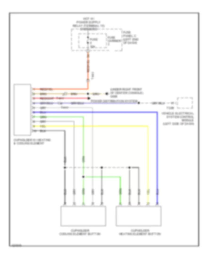
Heated And Cooled Cup Holder Wiring Diagram for Audi Q5 TDI Prestige 2014
List of elements for Heated And Cooled Cup Holder Wiring Diagram for Audi Q5 TDI Prestige 2014:
- (under right front of center console) g688
- Cupholder cooling element button
- Cupholder heating element button
- Cupholder w/ heating & cooling element
- Fuse 10a
- Fuse carrier
- Fuse panel c (left end of dash)
- Power distribution system
- T32b
- T4av
- Vehicle electrical system control module (left side of dash)