AIR CONDITIONING
Automatic A/C Wiring Diagram, Basic (1 of 2) for Audi Q7 Premium Plus 2013

List of elements for Automatic A/C Wiring Diagram, Basic (1 of 2) for Audi Q7 Premium Plus 2013:
- (behind center of dash) g45
- (behind right kick panel) g43
- (left side of engine compt) g640
- (rear of engine) coolant pump
- (right side of plenum chamber) g609
- 10a
- 12a
- 13a
- 3.0l sc
- 3.0l turbo diesel
- A/c compressor regulator valve
- Climatronic control module (in upper center console)
- Computer data lines system
- Coolant circulation pump relay (3.ol turbo diesel)
- Engine temperature sensor (on radiator outlet)
- Fresh air blower
- Fresh air blower control module
- Fresh air blower fuse 1 40a
- Fuse 10a
- Fuse 15a
- Fuse 30a
- Fuse 5a
- Fuse carrier
- Fuse panel c (right rear engine compt)
- High pressure sensor (evaporator expansion valve, under right side of dash)
- Hot at all times
- Left temperature flap motor & potentiometer/ actuator (left temperature flap motor: hvac housing)
- Relay & fuse carrier
- Relay & fuse panel e-box (left side of plenum chamber)
- Seats system
- Suppressor
- T10d
- T10f
- T16d
- T17k
- T20i
- T2q
- T3c
- T4t
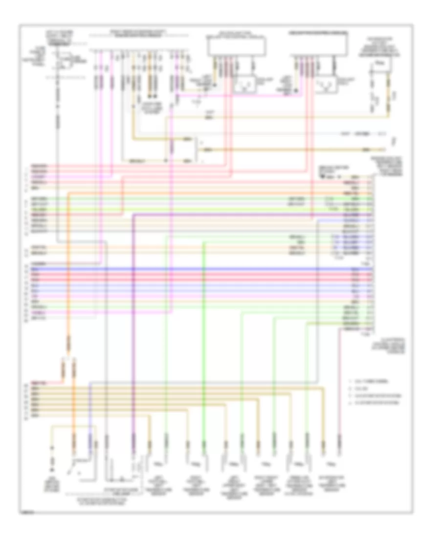
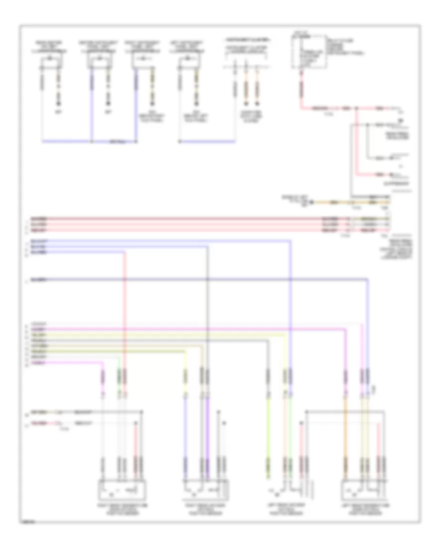
Automatic A/C Wiring Diagram, Basic (2 of 2) for Audi Q7 Premium Plus 2013
List of elements for Automatic A/C Wiring Diagram, Basic (2 of 2) for Audi Q7 Premium Plus 2013:
- (3.0l sc) auxiliary engine coolant pump relay
- (on coolant fan) coolant fan control module
- (or red)
- (right rear of engine)
- 10a
- 19a
- 19c
- 19d
- 19e
- 3.0l sc
- 3.0l turbo diesel
- After-run coolant pump
- Charge air cooling pump (3.0l sc)
- Computer data lines system
- Coolant fan
- Coolant fan 2
- Coolant fan control module 2
- Defroster flap motor & position sensor (defroster flap motor: hvac housing)
- Engine control module (right rear of engine compt)
- Engine coolant temperature sensor
- Evaporator vent temperature sensor
- Fuse 10a
- Fuse 15a
- Fuse 40a/ 60a
- Fuse 5a
- Fuse 60a/ 40a
- G645
- G671 (left front long member)
- Hot at all times
- Left footwell flap motor & position sensor
- Left side vent motor & position sensor (left side vent motor: hvac unit)
- Map controlled engine cooling thermostat (3.0l turbo diesel) (front of engine)
- Nca
- Recirculation flap motor (right side of dash)
- Relay & fuse panel e-box (left side of plenum chamber)
- T105
- T10ab
- T10c
- T10m
- T17d
- T60
- T91
- T94
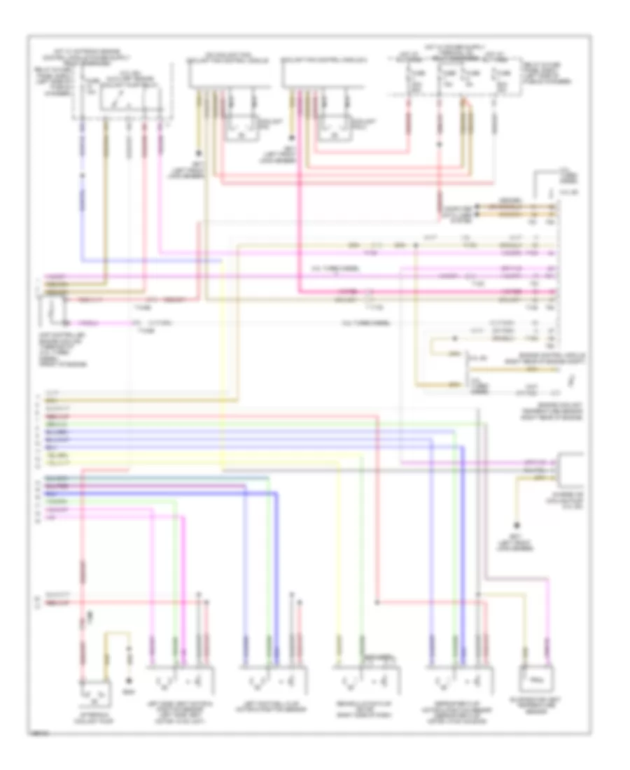
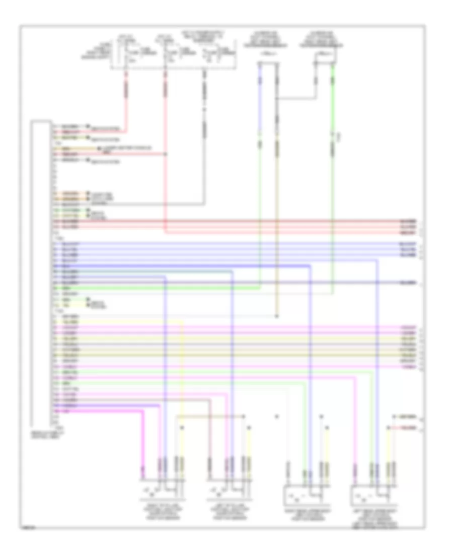
Automatic A/C Wiring Diagram, Comfort (1 of 4) for Audi Q7 Premium Plus 2013
List of elements for Automatic A/C Wiring Diagram, Comfort (1 of 4) for Audi Q7 Premium Plus 2013:
- (fresh air intake grille) air quality sensor
- (if equipped) automatic dimming interior rearview mirror
- A/c compressor regulator valve
- Climatronic control module (in upper center console)
- Computer data lines system
- Fresh air blower
- Fresh air blower control module
- G43 (behind right kick panel)
- G45 (behind center of dash)
- Humidity sensor
- Instrument panel temperature sensor
- Interior temperature sensor fan
- Left center vent motor & position sensor (hvac unit)
- Left footwell door motor & position sensor
- Left temperature door motor & potentiometer/ actuator
- Recirculation door motor & position sensor
- Right footwell door motor & position sensor
- Seats system
- T10f
- T16c
- T17k
- T20i
- T2q
- T3c
- T6ai
- W/ seat ventilation
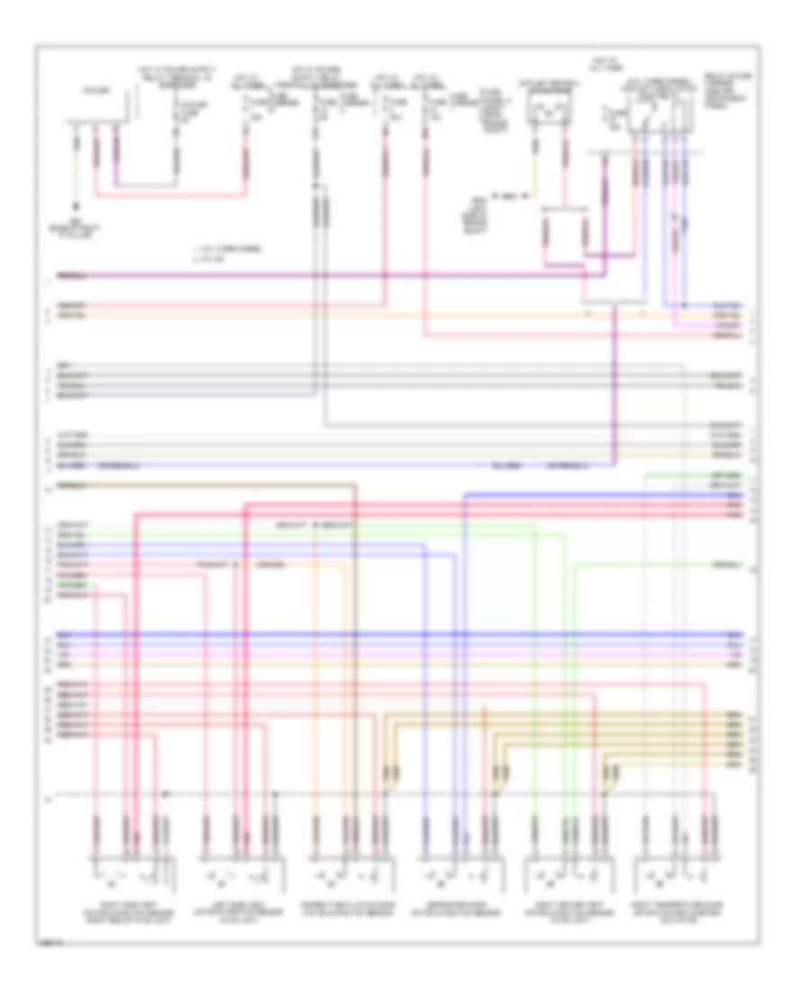
Automatic A/C Wiring Diagram, Comfort (2 of 4) for Audi Q7 Premium Plus 2013
List of elements for Automatic A/C Wiring Diagram, Comfort (2 of 4) for Audi Q7 Premium Plus 2013:
- (3.0l turbo diesel) coolant circulation pump relay
- 10a
- 12a
- 3.0l sc
- 3.0l turbo diesel
- Coolant recircu- lation pump
- Cooler
- Cooler fuse 5a
- Defroster door motor & position sensor
- Fuse 10a
- Fuse 15a
- Fuse 30a
- Fuse 40a
- Fuse 5a
- Fuse carrier
- Fuse panel c (right rear engine compt)
- G62 (base of right "c" pillar)
- G640 (left side of engine compt)
- Hot at all times
- Indirect ventilation door motor & position sensor
- Left side vent motor & position sensor (hvac unit)
- Pnk
- Relay & fuse carrier (center instrument panel)
- Right center vent motor & position sensor (hvac unit)
- Right side vent motor & position sensor (right end of hvac unit)
- Right temperature door motor & potentiometer/ actuator
- T10c
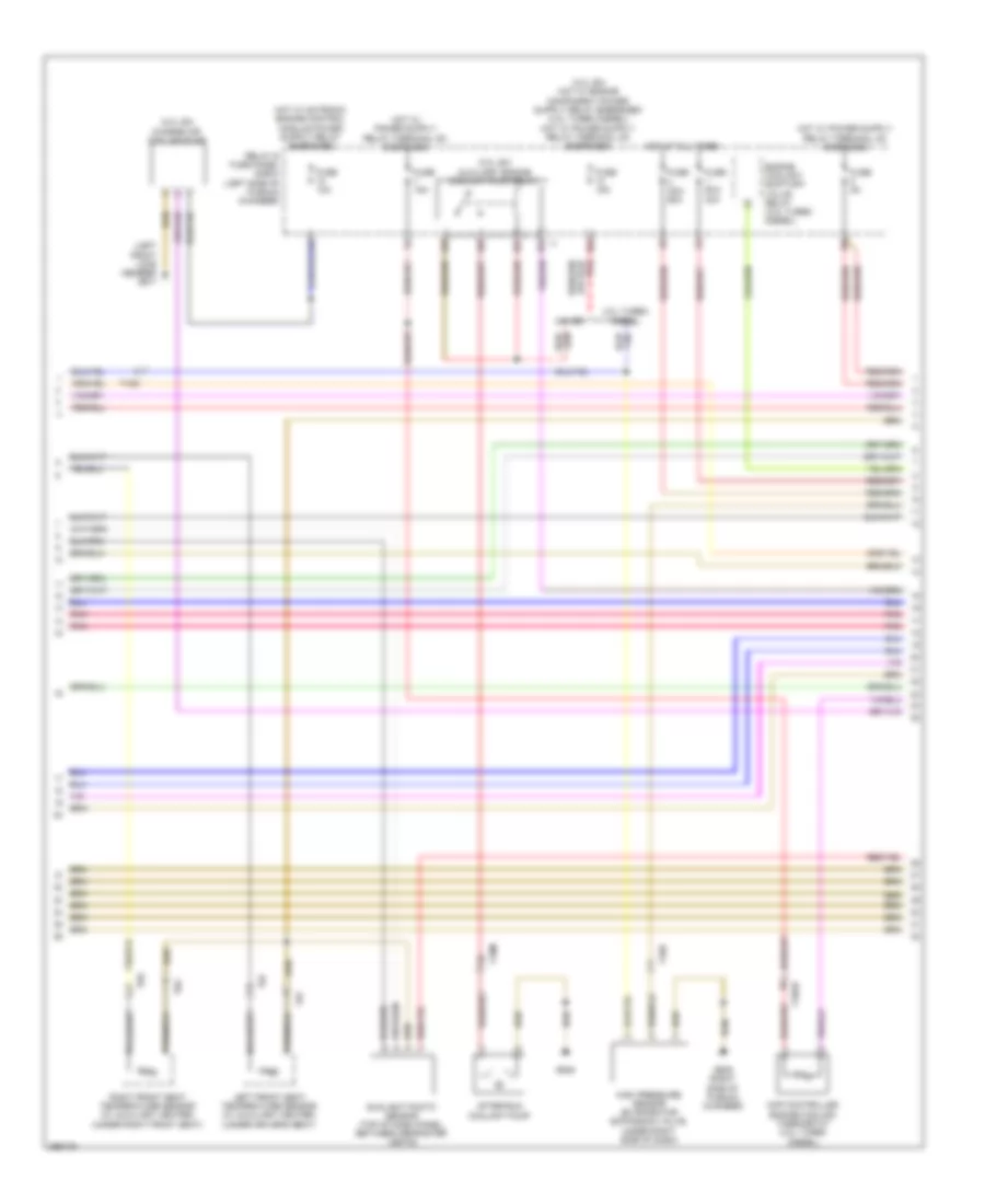
Automatic A/C Wiring Diagram, Comfort (3 of 4) for Audi Q7 Premium Plus 2013
List of elements for Automatic A/C Wiring Diagram, Comfort (3 of 4) for Audi Q7 Premium Plus 2013:
- (3.0l sc) auxiliary engine coolant pump relay
- (3.0l sc) charge air cooling pump
- (left front long member) g671
- 10a
- 13a
- 19a
- 19c
- 19d
- 19e
- 3.0l sc
- 3.0l turbo diesel
- After-run coolant pump
- Engine coolant shift-off valve relay (3.0l turbo diesel)
- Fuse 10a
- Fuse 15a
- Fuse 40a/ 60a
- Fuse 5a
- Fuse 60a/ 40a
- G609 (right side of plenum chamber)
- G645
- High pressure sensor (evaporator expansion valve, under right side of dash)
- Hot at all times
- Left front seat temperature sensor (w/ auxiliary heater) (under driver's seat)
- Map controlled engine cooling thermostat (3.0l turbo diesel)
- Pnk
- Relay & fuse panel e-box (left side of plenum chamber)
- Right front seat temperature sensor (w/ auxiliary heater) (under right front seat)
- Sunlight photo sensor (top of dash panel, between defroster vents)
- T10ab
- T10d
- T10m
- T6f
- T6g
Automatic A/C Wiring Diagram, Comfort (4 of 4) for Audi Q7 Premium Plus 2013
List of elements for Automatic A/C Wiring Diagram, Comfort (4 of 4) for Audi Q7 Premium Plus 2013:
- (behind center of dash) g45
- (left front long member) g671
- (on coolant fan) coolant fan control module
- (on radiator outlet) engine coolant temperature (ect) sensor (on radiator)
- (or red)
- (right rear of engine compt) engine control module
- 3.0l sc
- 3.0l turbo diesel
- Climatronic control module (in upper center console)
- Computer data lines system
- Coolant fan
- Coolant fan 2
- Coolant fan control module 2
- Engine coolant temperature (ect) sensor (right rear of engine)
- Evaporator vent temperature sensor
- Fresh air intake duct temperature sensor (hvac housing)
- Fuse 5a
- Fuse carrier
- Fuse panel b (left instrument panel)
- G45 (behind center of dash)
- Left footwell vent temperature sensor
- Left front upper body vent temperature sensor
- Nca
- Pnk
- Right footwell vent temperature sensor
- Right front upper body vent temperature sensor
- Start/stop mode button (w/ start/stop system)
- Start/stop mode ind lamp
- T105
- T10ab
- T12g
- T16d
- T17d
- T17k
- T60
- T91
- T94
- W/ start/stop system
- W/o start/stop system
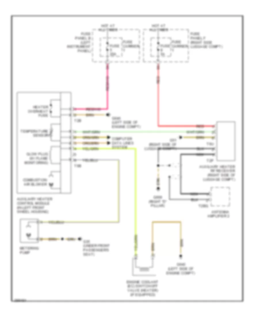
Auxiliary Heater Wiring Diagram for Audi Q7 Premium Plus 2013
List of elements for Auxiliary Heater Wiring Diagram for Audi Q7 Premium Plus 2013:
- Antenna amplifier 2
- Auxiliary heater control module (in left front wheel housing)
- Auxiliary heater rf receiver (right side of luggage compt)
- Combustion air blower
- Computer data lines system
- Engine coolant (ec) switch-off valve (heater) (if equipped)
- Fuse 20a
- Fuse 5a
- Fuse carrier
- Fuse panel b (left instrument panel)
- Fuse panel f (right side luggage compt)
- G35 (under front passenger's seat)
- G51 (right side of luggage compt)
- G640 (left side of engine compt)
- G669 (right "d" pillar)
- Glow plug (w/ flame monitoring)
- Heater overheat fuse
- Hot at all times
- Metering pump
- Nca
- Red
- T2b
- T2bq
- T2p
- T6b
- T6u
- Temperature sensor
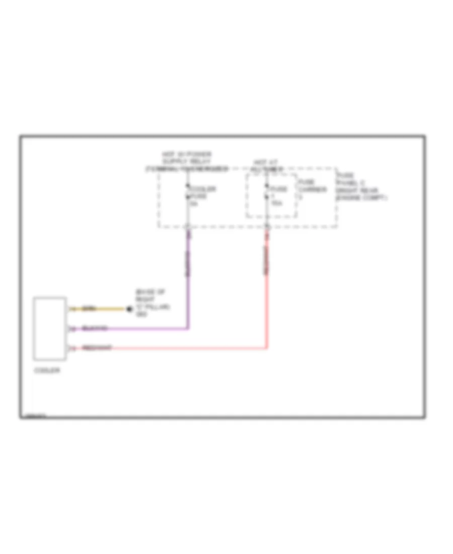
Cool Box Wiring Diagram for Audi Q7 Premium Plus 2013
List of elements for Cool Box Wiring Diagram for Audi Q7 Premium Plus 2013:
- (base of right "c" pillar) g62
- Cooler
- Cooler fuse 5a
- Fuse 15a
- Fuse carrier
- Fuse panel c (right rear engine compt)
- Hot at all times
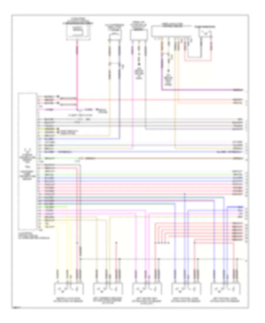
Rear A/C Wiring Diagram (1 of 2) for Audi Q7 Premium Plus 2013
List of elements for Rear A/C Wiring Diagram (1 of 2) for Audi Q7 Premium Plus 2013:
- (in rear air duct channel) left rear vent temperature sensor
- (in rear air duct channel) right rear vent temperature sensor
- (under center console) g687
- 12a
- Computer data lines system
- Fuse 10a
- Fuse 20a
- Fuse 5a
- Fuse carrier
- Fuse panel c (right rear engine compt)
- Hot at all times
- Left "b" pillar/ footwell shut-off door motor & position sensor
- Left rear upper body vent motor & position sensor (left rear upper body vent motor: hvac unit)
- Rear a/c display control head
- Right "b" pillar/ footwell shut-off door motor & position sensor
- Right rear upper body vent motor & position sensor
- Seats system
- T12h
- T16h
- T17h
- T20h
- T3h
Rear A/C Wiring Diagram (2 of 2) for Audi Q7 Premium Plus 2013
List of elements for Rear A/C Wiring Diagram (2 of 2) for Audi Q7 Premium Plus 2013:
- (base of left "c" pillar) g61
- Center instrument panel vent illumination bulb
- Computer data lines system
- Fresh air blower fuse 2 40a
- G43 (behind right kick panel)
- G44 (behind left kick panel)
- G67
- Hot at all times
- Instrument cluster
- Instrument cluster control module
- Left instrument panel vent illumination bulb
- Left rear air door motor & position sensor
- Left rear temperature door motor & position sensor
- Rear center air vent illumination bulb
- Rear fresh air blower
- Rear fresh air blower control module (left rear of luggage compt)
- Red
- Relay & fuse carrier (center instrument panel)
- Right instrument panel vent illumination bulb
- Right rear air door motor & position sensor
- Right rear temperature door motor & position sensor
- Suppressor
- T12k
- T17h
- T2r
- T4u