AIR CONDITIONING
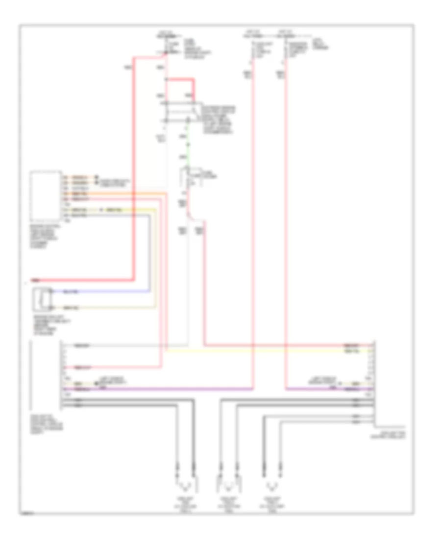
Automatic A/C Wiring Diagram, Convertible (1 of 3) for Audi RS 4 2008

List of elements for Automatic A/C Wiring Diagram, Convertible (1 of 3) for Audi RS 4 2008:
- 25a
- 44a
- Acc
- Climatronic control module
- Computer data lines system
- Defogger system
- Fresh air blower control module (below right side of dash)
- Fuse 10a
- Fuse 30a
- Fuse 35a
- Fuse 5a
- Fuse holder
- G33
- Hot at all times
- Hot in on or start
- Ignition/ starter switch
- Left vent temperature sensor
- Lock
- Right vent temperature sensor
- Seats system
- Start
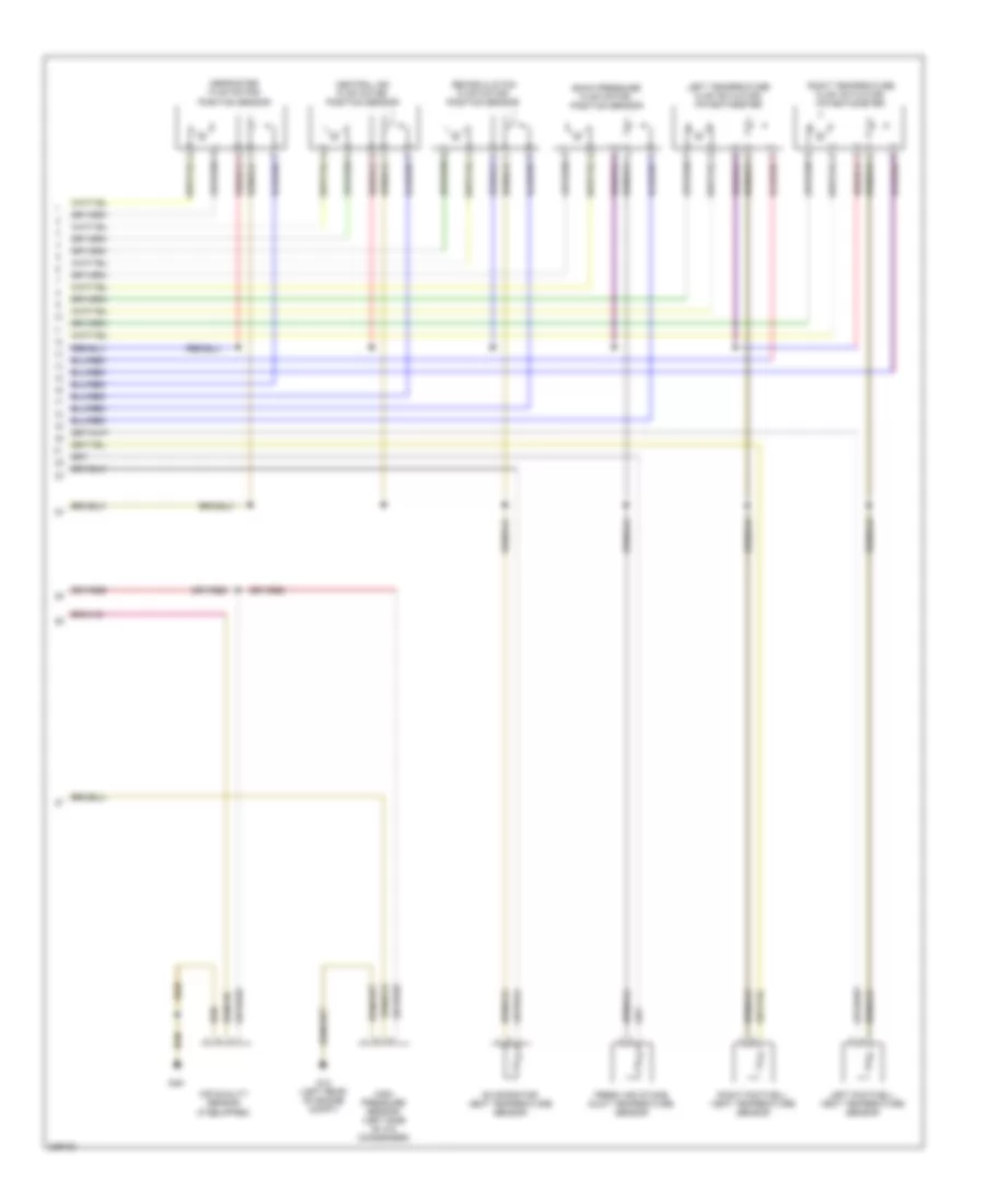
Automatic A/C Wiring Diagram, Convertible (2 of 3) for Audi RS 4 2008
List of elements for Automatic A/C Wiring Diagram, Convertible (2 of 3) for Audi RS 4 2008:
- Air quality sensor (if equipped)
- Back pressure flap motor/ position sensor
- Central air flap motor/ position sensor
- Defroster flap motor/ position sensor
- Evaporator vent temperature sensor
- Fresh air intake duct temperature sensor
- G12 (left rear of engine compt)
- G49
- High pressure sensor (left side of a/c condenser)
- Left footwell vent temperature sensor
- Left temperature flap actuator/ potentiometer
- Recirculation flap motor/ position sensor
- Right footwell vent temperature sensor
- Right temperature flap actuator/ potentiometer
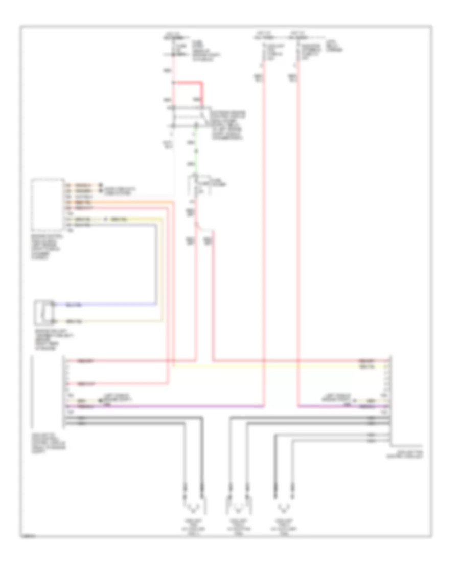
Automatic A/C Wiring Diagram, Convertible (3 of 3) for Audi RS 4 2008
List of elements for Automatic A/C Wiring Diagram, Convertible (3 of 3) for Audi RS 4 2008:
- (left side of engine compt) g26
- (rear of engine compt, in plenum)
- 4-pin relay carrier
- Computer data lines system
- Coolant fan (w/ cooling fan 1)
- Coolant fan 2 (w/ suction fan)
- Coolant fan 3 (w/ auxiliary fan)
- Coolant fan control module 2
- Coolant fan fuse 42 40a
- Coolant fc (fan control) control module (front of engine compt)
- Engine control module (ecm) (left engine compt plenum chamber, in e-box)
- Engine coolant temperature (ect) sensor (right rear of engine)
- Fuse 150a
- Fuse 5a
- Fuse holder
- Fuse strip
- Hot at all times
- Nca
- Radiator afterrun fuse 214 40a
- Red
- T2o
- T2p
- T60
- T6n
- T6o
- T94
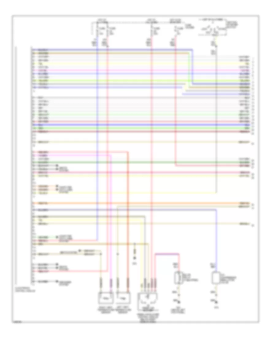
Automatic A/C Wiring Diagram, Except Convertible (1 of 3) for Audi RS 4 2008
List of elements for Automatic A/C Wiring Diagram, Except Convertible (1 of 3) for Audi RS 4 2008:
- 25a
- 44a
- A/c compressor regulator valve
- Acc
- Climatronic control module
- Computer data lines system
- Defogger system
- Fresh air blower
- Fresh air blower control module (below right side of dash)
- Fuse 10a
- Fuse 30a
- Fuse 35a
- Fuse 5a
- Fuse holder
- G18
- G33
- G44 (above left kick panel)
- Hot at all times
- Hot in on or start
- Ignition/ starter switch
- Left vent temperature sensor
- Lock
- Right vent temperature sensor
- Seats system
- Solar cells (if equipped)
- Start
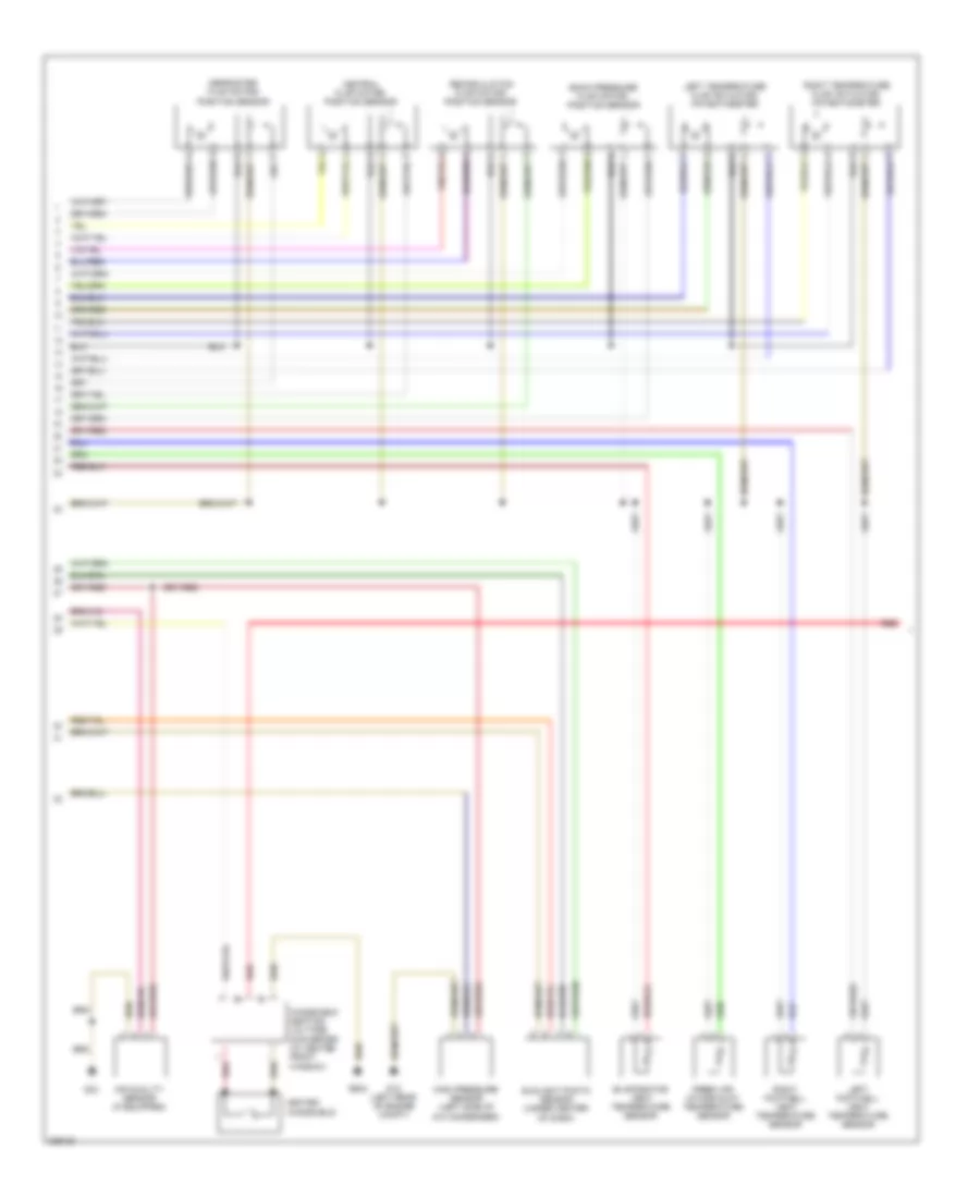
Automatic A/C Wiring Diagram, Except Convertible (2 of 3) for Audi RS 4 2008
List of elements for Automatic A/C Wiring Diagram, Except Convertible (2 of 3) for Audi RS 4 2008:
- + red
- Air quality sensor (if equipped)
- Back pressure flap motor/ position sensor
- Central flap motor/ position sensor
- Defroster flap motor/ position sensor
- Evaporator vent temperature sensor
- Fresh air intake duct temperature sensor
- G12 (left rear of engine compt)
- G33
- G624
- Heated windshield
- High pressure sensor (left side of a/c condenser)
- Left footwell vent temperature sensor
- Left temperature flap actuator/ potentiometer
- Recirculation flap motor/ position sensor
- Red
- Right footwell vent temperature sensor
- Right temperature flap actuator/ potentiometer
- Sunlight photo sensor (under center of dash)
- Windshield heating voltage converter (w/ heated front window)
Automatic A/C Wiring Diagram, Except Convertible (3 of 3) for Audi RS 4 2008
List of elements for Automatic A/C Wiring Diagram, Except Convertible (3 of 3) for Audi RS 4 2008:
- (left side of engine compt) g26
- (rear of engine compt, in plenum)
- 4-pin relay carrier
- Computer data lines system
- Coolant fan (w/ cooling fan 1)
- Coolant fan 2 (w/ suction fan)
- Coolant fan 3 (w/ auxiliary fan)
- Coolant fan control module 2
- Coolant fan fuse 42 40a
- Coolant fc (fan control) control module (front of engine compt)
- Engine control module (ecm) (left engine compt plenum chamber, in e-box)
- Engine coolant temperature (ect) sensor (right rear of engine)
- Fuse 150a
- Fuse 5a
- Fuse holder
- Fuse strip
- Hot at all times
- Nca
- Radiator afterrun fuse 214 40a
- Red
- T2o
- T2p
- T60
- T6n
- T6o
- T94