AIR CONDITIONING
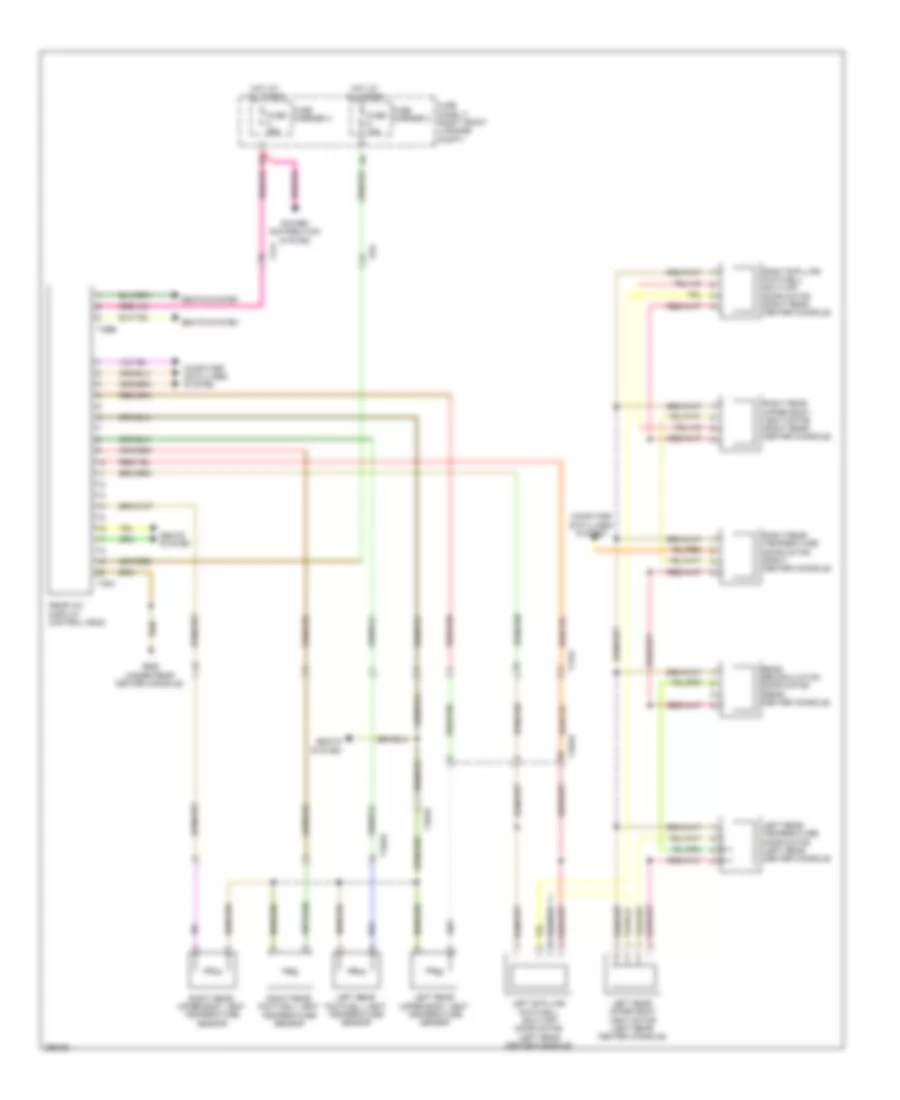
Automatic A/C Wiring Diagram (1 of 4) for Audi S8 2013

List of elements for Automatic A/C Wiring Diagram (1 of 4) for Audi S8 2013:
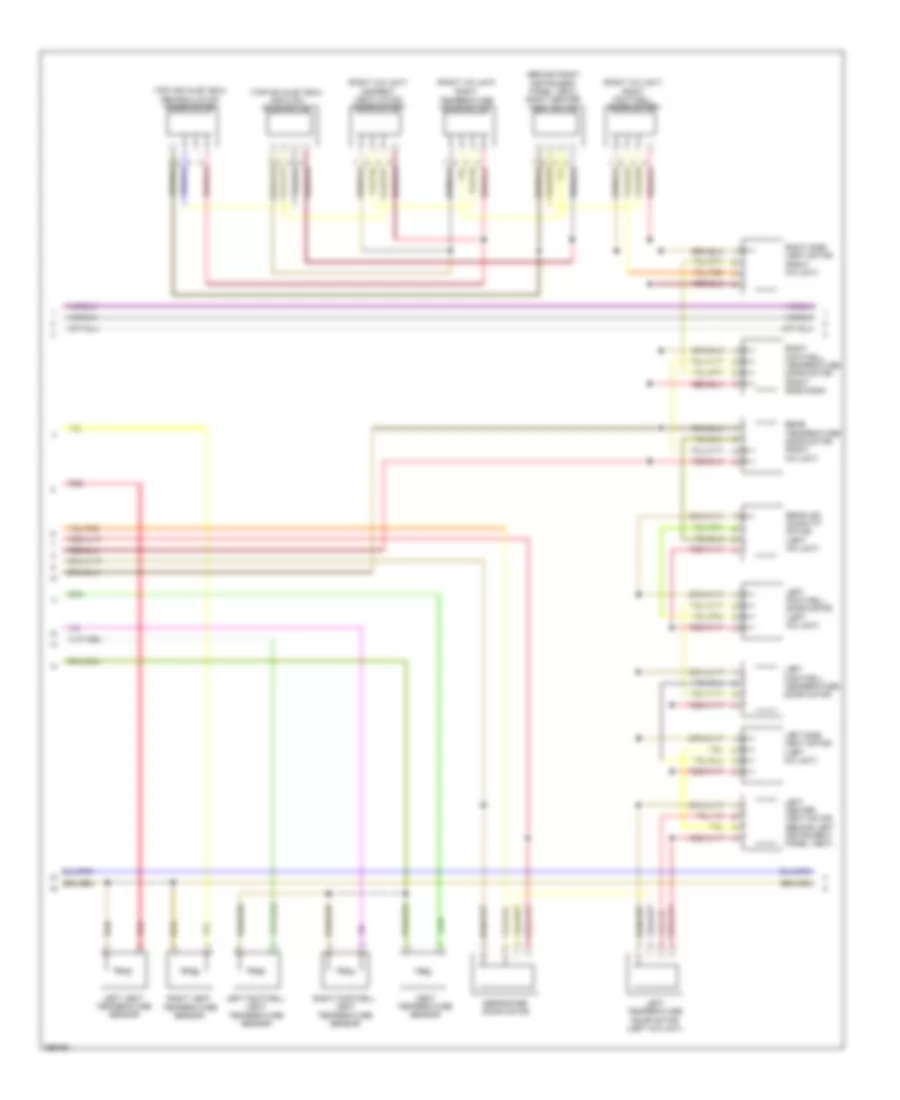
Automatic A/C Wiring Diagram (2 of 4) for Audi S8 2013
List of elements for Automatic A/C Wiring Diagram (2 of 4) for Audi S8 2013:
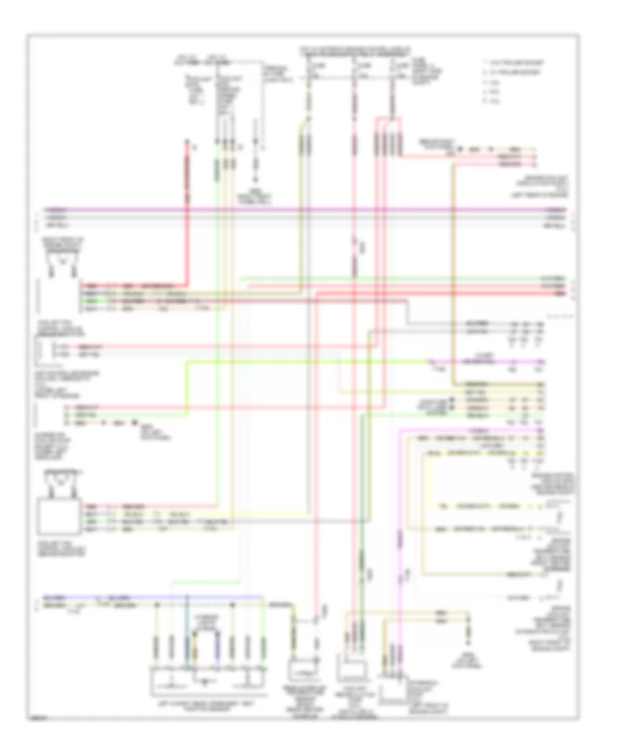
Automatic A/C Wiring Diagram (3 of 4) for Audi S8 2013
List of elements for Automatic A/C Wiring Diagram (3 of 4) for Audi S8 2013:
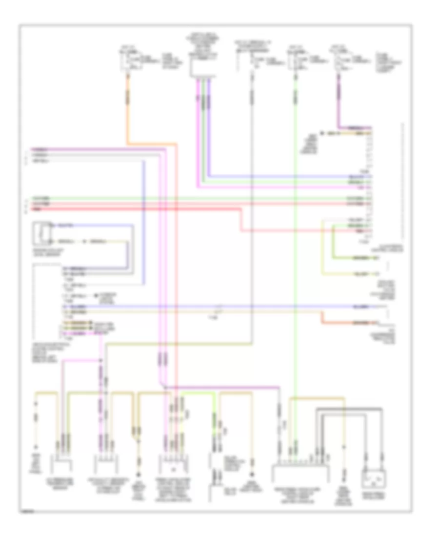
Automatic A/C Wiring Diagram (4 of 4) for Audi S8 2013
List of elements for Automatic A/C Wiring Diagram (4 of 4) for Audi S8 2013:
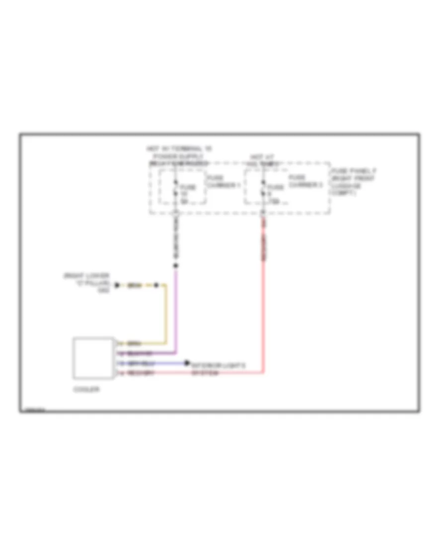
Cool Box Wiring Diagram for Audi S8 2013
List of elements for Cool Box Wiring Diagram for Audi S8 2013:
Rear A/C Wiring Diagram for Audi S8 2013
List of elements for Rear A/C Wiring Diagram for Audi S8 2013: