AIR CONDITIONING
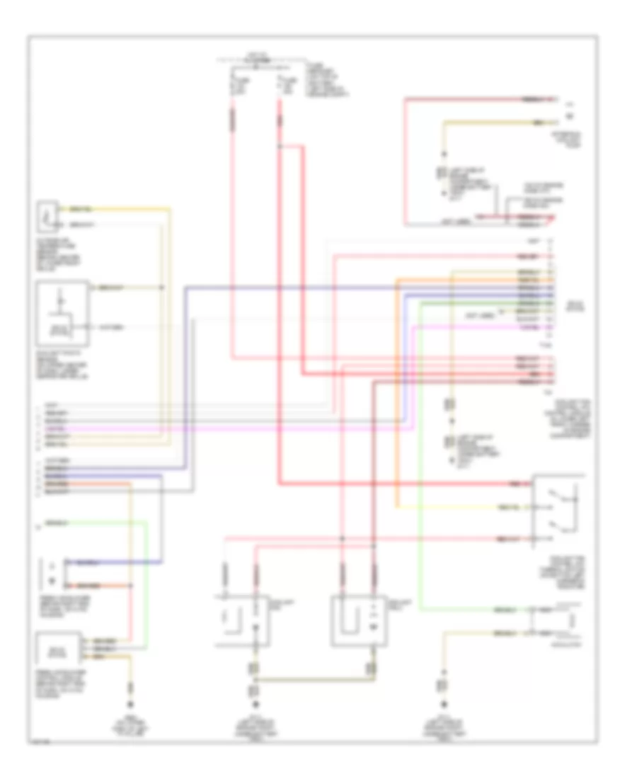
Automatic A/C Wiring Diagram (1 of 2) for Audi TT Quattro 2001

List of elements for Automatic A/C Wiring Diagram (1 of 2) for Audi TT Quattro 2001:
- (not used)
- A/c control head
- A10
- A11
- A12
- B10
- B11
- B12
- B13
- B14
- B15
- B16
- B17
- B18
- B19
- B20
- Back pressure flap motor position sensor (behind right end of dash, on hvac housing)
- C10
- C11
- C12
- C13
- C14
- C15
- C16
- Central flap motor position sensor (beneath right side of dash, on left side of hvac housing)
- D10
- D11
- D12
- D13
- D14
- D15
- D16
- Data link connector (dlc) (partial) (below left side of steering column)
- Footwell/defrost flap motor position sensor (behind right side of dash, on left side of hvac housing)
- Fresh air intake duct temperature sensor (in hvac intake duct, on right side of engine compartment)
- Fuse 10a
- Fuse 25a
- Fuse 5a
- Fuse 7.5a
- Fuse panel (on left end of dash)
- G111 (left front of engine compt, under battery)
- G204 (left of steering column)
- High pressure sensor
- Hot at all times
- Hot in run or start
- Hot w/light switch in park or head position
- Hot w/load reduction relay energized
- Instrument cluster
- Interior lights system
- Motronic engine control module (ecm) (in center of plenum, between firewall & windshield base)
- Outlet temperature floor outlet sensor (behind left center of dash, on hvac housing)
- Outside air temperature display
- Solid state
- T32
- T32a
- Temperature regulator flap motor position sensor (beneath right side of dash, on lower left side of hvac housing)
Automatic A/C Wiring Diagram (2 of 2) for Audi TT Quattro 2001
List of elements for Automatic A/C Wiring Diagram (2 of 2) for Audi TT Quattro 2001:
- (left side of engine compartment, under battery tray) g111
- (not used)
- 132 kw engine, code atc
- 165 kw engine, code amu
- A/c clutch
- After-run coolant pump
- Coolant fan
- Coolant fan 2
- Coolant fan control (fc) control module (in lower left front corner of engine compartment)
- Coolant fan control (fc) thermal switch (on bottom left corner of radiator)
- Fresh air blower (behind right end of dash, on hvac housing)
- Fresh air blower control module (behind right end of dash, on hvac housing)
- Fuse 30a
- Fuse bracket (on top of battery, left side of engine compt)
- G111 (left side of engine compt, under battery tray)
- G900 (on lower part of left "a" pillar)
- Hot at all times
- Nca
- Outside air temperature sensor (behind center of lower front grille)
- Red
- Solid state
- Sunlight photo sensor (on upper center of dash, under defroster grille)
- T14b
- T4f