AIR CONDITIONING
Automatic A/C Wiring Diagram (1 of 2) for Audi TT Quattro 2009

List of elements for Automatic A/C Wiring Diagram (1 of 2) for Audi TT Quattro 2009:
- 12a
- A/c compressor regulator valve
- Climatronic control module (in a/c control head)
- Computer data lines system
- Evaporator vent temperature sensor (lower right side of evaporator)
- Fresh air blower
- Fresh air blower control module (on fresh air blower motor)
- Fuse 25a
- Fuse 40a
- Fuse holder
- Fuse panel sb (left side of engine compt)
- G43 (lower right "a" pillar)
- G44 (lower left "a" pillar)
- G672 (on left front long member)
- Hot at all times
- Left footwell vent temperature sensor (top left side of hvac unit)
- Left front seat temperature sensor (in seat bottom)
- Left front upper body outlet temperature sensor (left side of dash)
- Right footwell vent temperature sensor (top right side of hvac unit)
- Right front seat temperature sensor
- Seats system
- Solid state
- Sunlight photo sensor
- T12k
- T16c
- T16d
- T20k
- T3ae
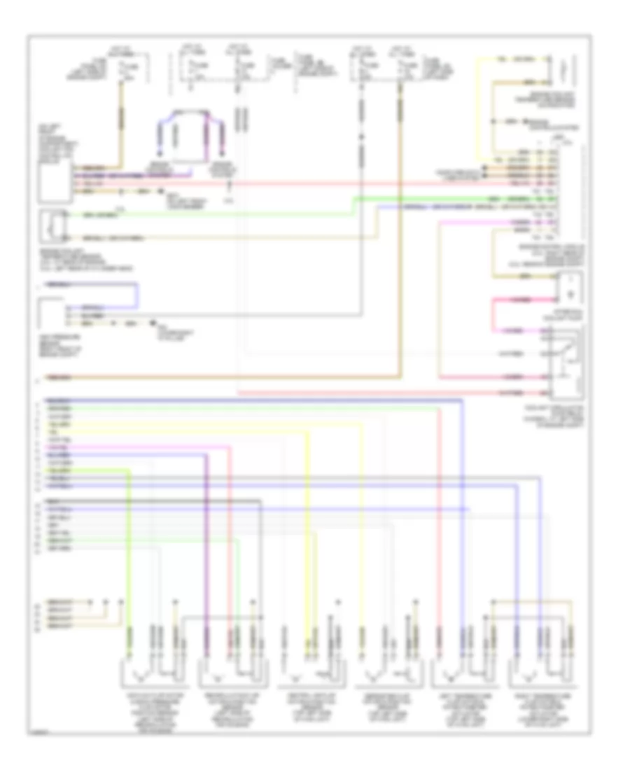
Automatic A/C Wiring Diagram (2 of 2) for Audi TT Quattro 2009
List of elements for Automatic A/C Wiring Diagram (2 of 2) for Audi TT Quattro 2009:
- (on left front of engine compartment) coolant fan control (fc) module
- 10a
- 16a
- 2.0l
- 3.2l
- After run coolant pump
- Air flow flap motor & back pressure flap motor position sensor (left side of recirculating air housing)
- Central air flap motor & position sensor (top left side of hvac unit)
- Computer data lines system
- Coolant circulation pump relay (in e-box, at left side of engine compt)
- Defroster flap motor & position sensor (top left side of hvac unit)
- Engine control module (2.0l: right rear of engine compt) (3.2l: rear of engine compt)
- Engine controls system
- Engine coolant temperature sensor (2.0l: at rear of engine) (3.2l: left rear of cylinder head)
- Engine coolant temperature sensor (on radiator)
- Fuse 10a
- Fuse 5a
- Fuse 60a
- Fuse holder
- Fuse panel sa (left side of engine compt)
- Fuse panel sb (left side of engine compt)
- Fuse panel sc (left side of dash)
- G43 (lower right "a" pillar)
- G672 (on left front long member)
- High pressure sensor (right front of engine compt)
- Hot at all times
- Left temperature flap motor & potentiometer/ actuator (top left side of hvac unit)
- Recirculation flap motor & position sensor (left side of recirculating air housing)
- Right temperature flap motor & potentiometer/ actuator (lower right side of hvac unit)
- T40
- T60
- T81
- T94