AIR CONDITIONING
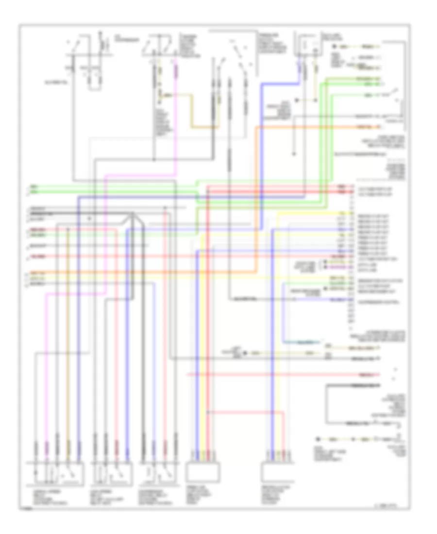
Air Conditioning Wiring Diagrams (1 of 3) for BMW 530iT 1994

List of elements for Air Conditioning Wiring Diagrams (1 of 3) for BMW 530iT 1994:
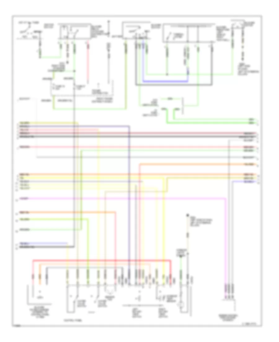
Air Conditioning Wiring Diagrams (2 of 3) for BMW 530iT 1994
List of elements for Air Conditioning Wiring Diagrams (2 of 3) for BMW 530iT 1994:
Air Conditioning Wiring Diagrams (3 of 3) for BMW 530iT 1994
List of elements for Air Conditioning Wiring Diagrams (3 of 3) for BMW 530iT 1994: