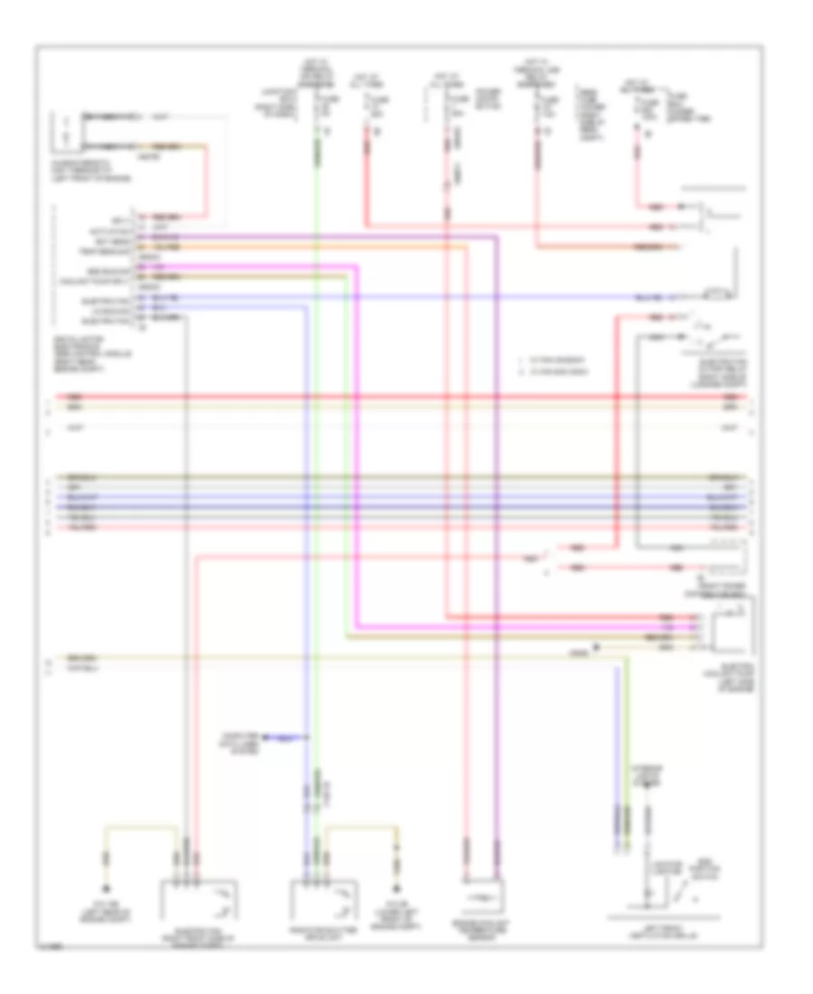
AIR CONDITIONING
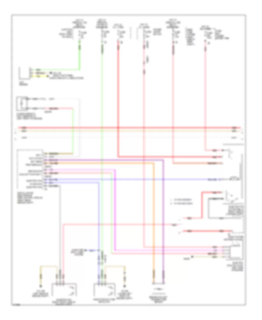
Automatic A/C Wiring Diagram, with Rear Automatic Climate Control (1 of 4) for BMW 535i GT 2010

List of elements for Automatic A/C Wiring Diagram, with Rear Automatic Climate Control (1 of 4) for BMW 535i GT 2010:
- (top center of dash) rain/driving lights/ condensation/ solar sensor
- Activation ioniser
- Auc sensor
- Basic variant roof functions module
- Computer data lines system
- Coolant pressure sensor (behind right front wheel)
- Electro- chromic interior rear view 1b mirror
- End pos sw sig
- End position switch
- Front center ventilation grille
- Fuse 5a
- Fuse 7.5a
- Gnd
- Gnd ioniser
- Heating/air conditioning system
- High variant roof functions module
- Hot w/ bi-stable relay energized
- Hot w/ terminal 15n relay energized
- Hot w/ terminal 30b relay energized
- Interior lights system
- Ioniser
- Junction box (right side of dash)
- Junction box electronics
- K-can bus sig
- Left adjuster sig
- Left end pos sw sig
- Left end position switch
- Left stratification actuator
- Lin bus sig
- Locator lighting
- Power distribution system
- Red
- Right adjuster sig
- Right end pos sw sig
- Right end position switch
- Right front ventilation grille
- Right stratification actuator
- Sens gnd
- Sens sig
- Sig evaporator temp sens
- Sply volt
- Temp sens
- W/ basic variant
- W/ high variant
- Wiper module
- Z10 11b (right kick panel)
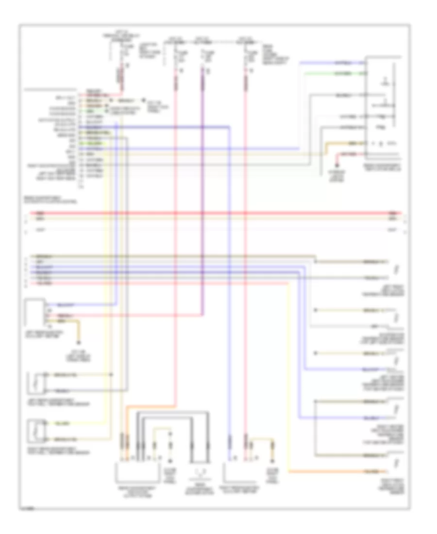
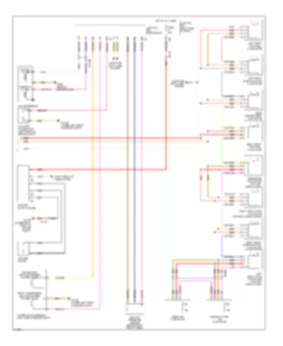
Automatic A/C Wiring Diagram, with Rear Automatic Climate Control (2 of 4) for BMW 535i GT 2010
List of elements for Automatic A/C Wiring Diagram, with Rear Automatic Climate Control (2 of 4) for BMW 535i GT 2010:
- Activation
- Bsd bus sig
- Characteristic map thermostat (left front of engine)
- Computer data lines system
- Coolant pump sply
- Digital motor electronics (dme) control module (right rear engine compt)
- Ect sens
- Electric coolant pump (left side of engine)
- Electric fan
- Electric fan (right front side of engine compt)
- Electric fan cutoff relay (right side of luggage compt)
- End position switch
- Engine coolant temperature sensor
- Front power distribution box
- Fuse 100a
- Fuse 50a
- Fuse 5a
- Fuse 60a
- Fuse 7.5a
- Fuse box (under spare tire)
- Hot at all times
- Hot w/ terminal 15n relay energized
- Hot w/ terminal 30b relay energized
- Interior lights system
- Junction box (right side of dash)
- Left front ventilation grille
- Lin bus sig
- Locator lighting
- Nca
- Power distri- bution
- Radiator shutter drive unit
- Rear fuse holder (right side of rear compt)
- Red
- Sply
- Temp sens sig
- W/ fan 400/600w
- W/ fan 800/1000w
- X148 1b
- X60002
- X60003
- X60183
- X60571
- X62790
- X6455
- Z10 15b (left rear of engine compt)
- Z10 2b (lower left front of engine compt)
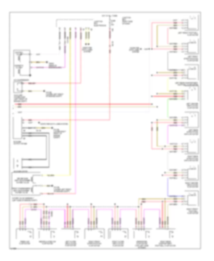
Automatic A/C Wiring Diagram, with Rear Automatic Climate Control (3 of 4) for BMW 535i GT 2010
List of elements for Automatic A/C Wiring Diagram, with Rear Automatic Climate Control (3 of 4) for BMW 535i GT 2010:
- 12b
- Activation output
- Computer data lines system
- Evaporator temperature sensor (top left side of dash)
- Fuse 20a
- Fuse 30a
- Fuse 5a
- Gnd
- Hot at all times
- Hot w/ terminal 30b relay energized
- Interior lights system
- Junction box (right side of dash)
- K-can bus sig
- Left front ventilation temperature sensor
- Left heater heat exchanger temperature sensor (top center of dash)
- Left rear compartment footwell temperature sensor
- Left rear electric auxiliary heater
- Left sig temp sens
- Lr aux htr
- Nca
- Rear compartment automatic climate control
- Rear compartment blower motor
- Rear compartment fan motor output stage
- Rear compartment ventilation grille
- Rear fuse holder (right side of rear compt)
- Red
- Right front ventilation temperature sensor
- Right heater heat exchanger temperature sensor (top center of dash)
- Right rear compartment footwell temperature sensor
- Right rear electric auxiliary heater
- Right sig temp sens
- Rr aux htr
- Sens gnd
- Sig
- Sig right sig stratification adjuster
- Sply
- Sply volt
- Z10 11b (right kick panel)
- Z10 14b (left side of cargo area)
- Z10 6b (right kick panel)
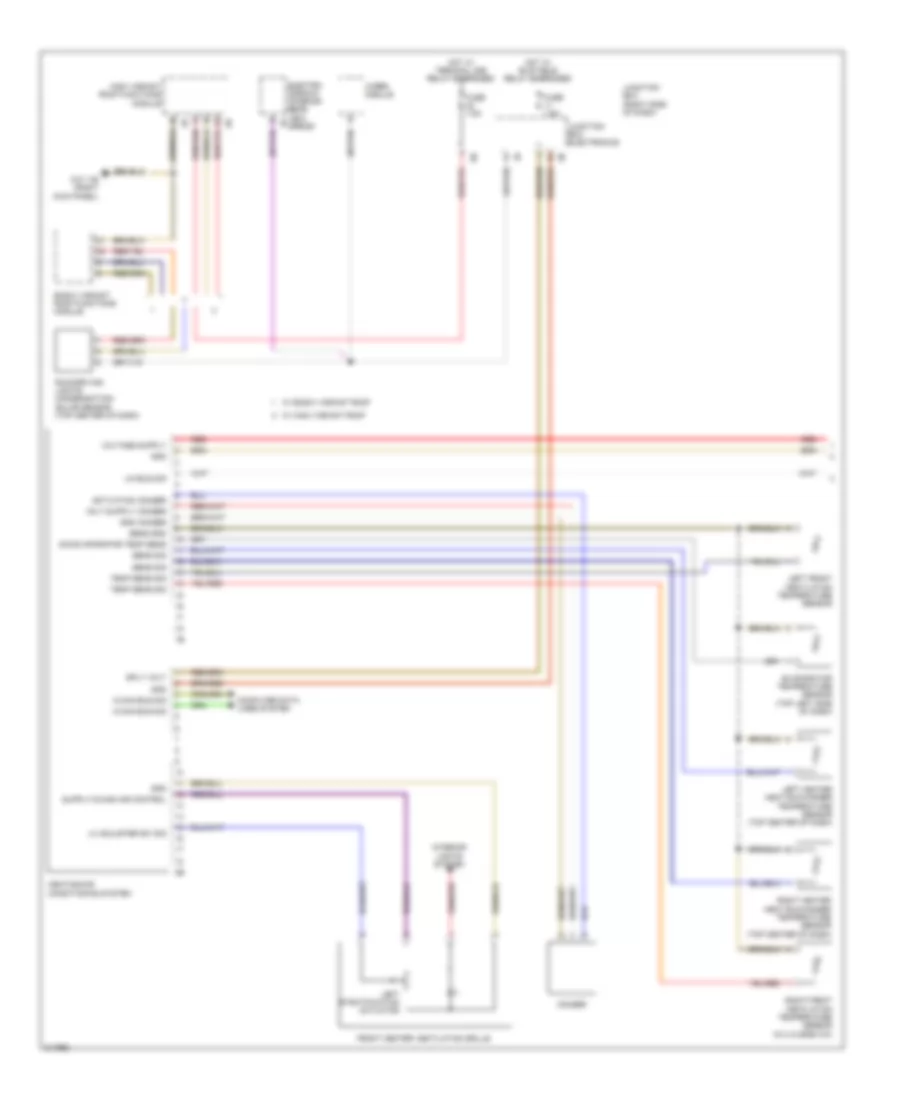
Automatic A/C Wiring Diagram, with Rear Automatic Climate Control (4 of 4) for BMW 535i GT 2010
List of elements for Automatic A/C Wiring Diagram, with Rear Automatic Climate Control (4 of 4) for BMW 535i GT 2010:
- 13b
- A/c compressor
- Auxiliary water pump (left front of engine compt)
- Blower motor
- Blower output stage
- Computer data lines system
- Control valve
- Defroster flap motor (top left side of dash)
- Driver side heat exchanger water valve
- Fresh air flap motor
- Front passenger's heat exchanger water valve
- Fuse 40a
- Hot at all times
- Junction box (right side of dash)
- Junction box electronics
- Left center ventilation flap motor
- Left front footwell flap motor
- Left front stratification flap motor
- Left outer ventilation flap motor
- Left rear compartment footwell flap motor
- Left rear stratifying air flap motor
- Magnetic clutch
- N2 1b
- Nca
- Recirculated air flap motor
- Red
- Right center ventilation flap motor
- Right front footwell flap motor
- Right front stratification flap motor
- Right outer ventilation flap motor
- Right rear compartment footwell flap motor
- Right rear stratifying air flap motor
- Water valve assembly (left side of engine compt)
- X01001
- X13 10b
- X6454 (rear of engine block)
- Z10 2b (lower left front of engine compt)
- Z10 3b (lower right front of engine compt)
Automatic A/C Wiring Diagram, without Rear Automatic Climate Control (1 of 3) for BMW 535i GT 2010
List of elements for Automatic A/C Wiring Diagram, without Rear Automatic Climate Control (1 of 3) for BMW 535i GT 2010:
- Activation ioniser
- Basic variant roof functions module
- Computer data lines system
- Electro- chromic interior rear view 1b mirror
- Evaporator temperature sensor (top left side of dash)
- Front center ventilation grille
- Fuse 7.5a
- Gnd
- Gnd ioniser
- Heating/air conditioning system
- High variant roof functions module
- Hot w/ bi-stable relay energized
- Hot w/ terminal 30b relay energized
- Interior lights system
- Ioniser
- Junction box (right side of dash)
- Junction box electronics
- K-can bus sig
- Left front ventilation temperature sensor
- Left heater heat exchanger temperature sensor (top center of dash)
- Left stratification actuator
- Lh adjuster sw sig
- Lin bus sig
- Rain/driving lights/ condensation/ solar sensor (top center of dash)
- Red
- Right front ventilation temperature sensor (w/ 2.5 zone a/c)
- Right heater heat exchanger temperature sensor (top center of dash)
- Sens gnd
- Sens sig
- Sig evaporator temp sens
- Sply volt
- Temp sens sig
- W/ basic variant roof
- W/ high variant roof
- Wiper module
- Z10 11b (right kick panel)
Automatic A/C Wiring Diagram, without Rear Automatic Climate Control (2 of 3) for BMW 535i GT 2010
List of elements for Automatic A/C Wiring Diagram, without Rear Automatic Climate Control (2 of 3) for BMW 535i GT 2010:
- Activation
- Auc sensor
- Bsd bus sig
- Characteristic map thermostat (left front of engine)
- Computer data lines system
- Coolant pump sply
- Digital motor electronics (dme) control module (right rear engine compt)
- Ect sens
- Electric coolant pump (left side of engine)
- Electric fan
- Electric fan (right front side of engine compt)
- Electric fan cutoff relay (right side of luggage compt)
- Engine coolant temperature sensor
- Front power distribution box
- Fuse 100a
- Fuse 50a
- Fuse 5a
- Fuse 60a
- Fuse 7.5a
- Fuse box (under spare tire)
- Hot at all times
- Hot w/ terminal 15n relay energized
- Hot w/ terminal 30b relay energized
- Junction box (right side of dash)
- Lin bus sig
- Nca
- Power distri- bution
- Radiator shutter drive unit
- Rear fuse holder (right side of rear compt)
- Red
- Sply
- Temp sens sig
- W/ fan 400/600w
- W/ fan 800/1000w
- X148 1b
- X60002
- X60003
- X60183
- X60571
- X62790
- X6455
- Z10 11b (right kick panel)
- Z10 15b (left rear of engine compt)
- Z10 2b (lower left front of engine compt)
Automatic A/C Wiring Diagram, without Rear Automatic Climate Control (3 of 3) for BMW 535i GT 2010
List of elements for Automatic A/C Wiring Diagram, without Rear Automatic Climate Control (3 of 3) for BMW 535i GT 2010:
- 13b
- A/c compressor
- Auxiliary water pump (left front of engine compt)
- Blower motor
- Blower output stage
- Computer data lines system
- Control valve
- Coolant pressure sensor (behind right front wheel)
- Defroster flap motor (top left side of dash)
- Driver side heat exchanger water valve
- Fresh air flap motor
- Front passenger's heat exchanger water valve
- Fuse 40a
- Hot at all times
- Junction box (right side of dash)
- Junction box electronics
- Left front footwell flap motor
- Left front stratification flap motor
- Left ventilation flap motor (top left side of dash)
- Magnetic clutch
- N2 1b
- Nca
- Rear compartment flap motor
- Recirculated air flap motor
- Red
- Right front footwell flap motor
- Right front stratification flap motor
- Right ventilation flap motor (top right side of dash)
- Water valve assembly (left side of engine compt)
- X01001
- X13 10b
- X6454 (rear of engine block)
- Z10 2b (lower left front of engine compt)
- Z10 3b (lower right front of engine compt)
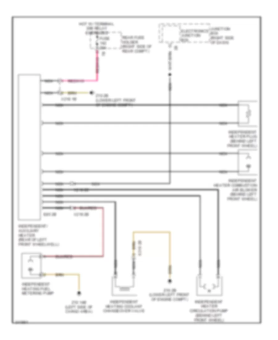
Independent Heating Wiring Diagram for BMW 535i GT 2010
List of elements for Independent Heating Wiring Diagram for BMW 535i GT 2010:
- E85 2b
- Electronics junction box
- Fuse 20a
- Hot w/ terminal 30b relay energized
- Independent heater circulation pump (behind left front wheel)
- Independent heater combustion air blower (behind left front wheel)
- Independent heater plug (behind left front wheel)
- Independent heating coolant changeover valve
- Independent heating fuel metering pump
- Independent/ auxiliary heater (rear of left front wheelwell)
- Junction box (right side of dash)
- Nca
- Rear fuse holder (right side of rear compt)
- X218 1b
- X218 2b
- Z10 14b (left side of cargo area)
- Z10 2b (lower left front of engine compt)