AIR CONDITIONING
3.8L VIN 2
3.8L VIN 2, Automatic A/C Wiring Diagram (1 of 2) for Buick Allure CXL 2009

List of elements for 3.8L VIN 2, Automatic A/C Wiring Diagram (1 of 2) for Buick Allure CXL 2009:
- (left rear of engine) g115
- (part of a/c compressor) a/c compressor clutch
- (right front of engine compt) g100
- (w/ california pzev emission system) j114
- A/c clu diode
- A/c clutch fuse 13 10a
- A/c comp relay
- A/c request ind
- A10
- A11
- A12
- A18
- A19
- Air temp a
- Air temp b
- Auto
- Battery
- Blower motor sw
- C18
- C19
- Class 2 serial
- Computer data lines system
- Defogger
- E10
- Fan 1 fuse 29 30a
- Fan 1 relay
- Fan 2 fuse 32 30a
- Fan 2 relay
- Fan 3 relay
- G200 (left side of dash)
- G202 (left side of dash)
- Ground
- High
- Hot at all times
- Hot w/ ign 1 relay energized
- Hvac control module (center of dash)
- Ign 1 volt
- Illum
- Ind
- Interior lights system
- J211
- J213
- K14
- K15
- K18
- K19
- L14
- Left air temperature actuator (left side of dash, on hvac module)
- Logic
- Low
- Low ref
- Lower left air temperature sensor (behind hvac control module)
- Lower right air temperature sensor (behind hvac control module)
- M14
- M15
- M18
- M19
- Mode actuator (lower left side of hvac assembly)
- Mode door a
- Mode switch
- Off
- Pnk
- Position sig
- Rear defogger switch
- Recirc a
- Recirc b
- Recirculation
- Recirculation actuator (right side of hvac assembly)
- Recirculation switch
- Request switch a/c
- Right air temperature actuator (right side of hvac module)
- Sensor sig
- Speed ctrl
- Tan
- Temperature control sw
- Underhood fuse block (right front strut tower)
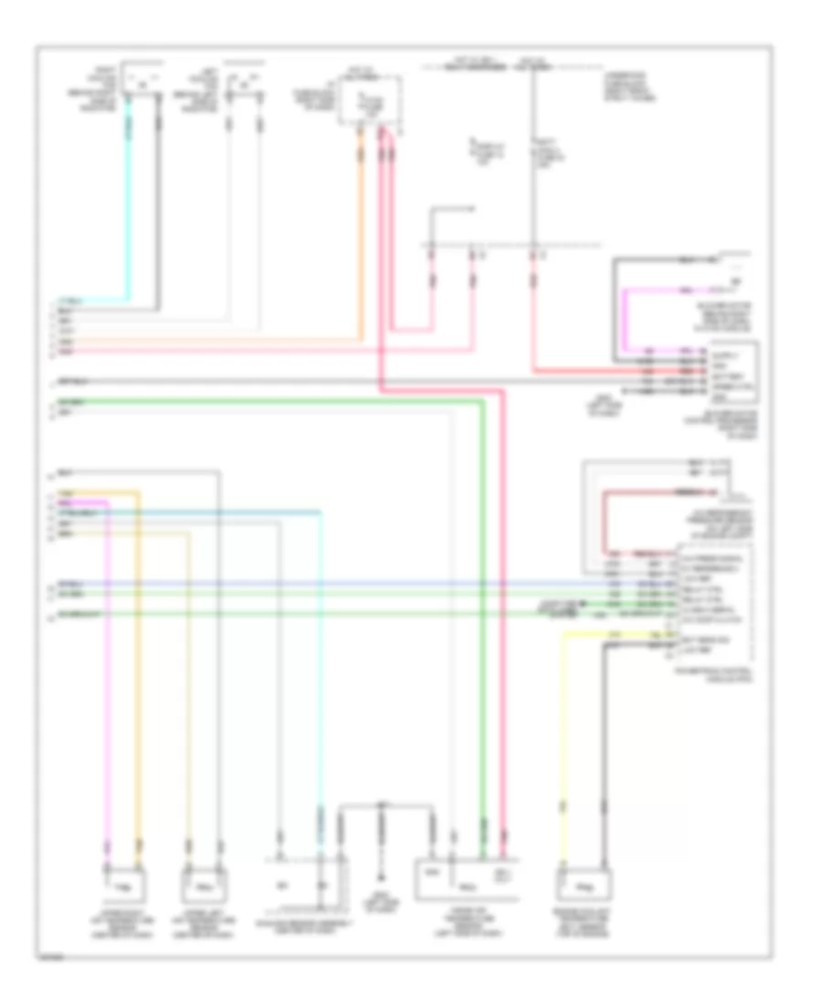
3.8L VIN 2, Automatic A/C Wiring Diagram (2 of 2) for Buick Allure CXL 2009
List of elements for 3.8L VIN 2, Automatic A/C Wiring Diagram (2 of 2) for Buick Allure CXL 2009:
- 5v reference 2
- A/c comp clutch
- A/c press signal
- A/c refrigerant pressure sensor (on left side of engine compt)
- Batt main 4 fuse 30 30a
- Battery
- Blower motor (behind right side of dash, in hvac module)
- Blower motor control processor (right side of dash)
- Class 2 serial
- Computer data lines system
- D11
- Display fuse 18 10a
- Ect sens sig
- Engine coolant temperature (ect) sensor (top of engine)
- G200 (left side of dash)
- G202 (left side of dash)
- Gnd
- Hot at all times
- Hot w/ ign 1 relay energized
- Hvac fuse 10a
- I/p fuse block (right side of dash)
- Ign 1 volt
- Inside air temperature sensor (left side of dash)
- J211
- Left cooling fan (behind left side of radiator)
- Low ref
- Pnk
- Powertrain control module (pcm)
- Red
- Relay ctrl
- Right cooling fan (behind right side of radiator)
- Speed ctrl
- Sunload sensor assembly (center of dash)
- Tan
- Underhood fuse block (right front strut tower)
- Upper left air temperature sensor (center of dash)
- Upper right air temperature sensor (center of dash)
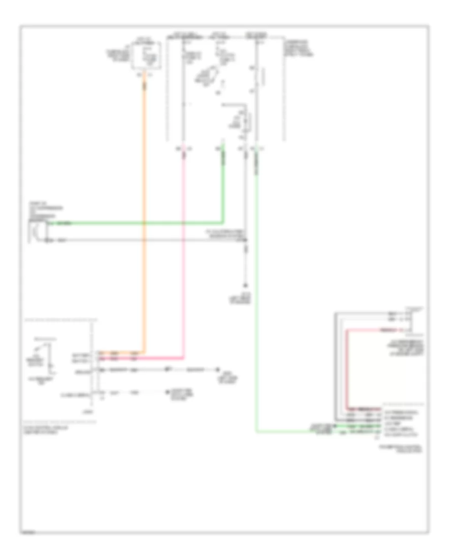
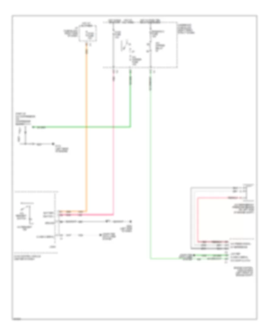
3.8L VIN 2, Compressor Wiring Diagram for Buick Allure CXL 2009
List of elements for 3.8L VIN 2, Compressor Wiring Diagram for Buick Allure CXL 2009:
- (part of a/c compressor) a/c compressor clutch
- (w/ california pzev emission system) j114
- 5v reference
- A/c clu diode
- A/c clutch fuse 13 10a
- A/c comp clutch
- A/c comp relay
- A/c press signal
- A/c refrigerant pressure sensor (on left side of engine compt)
- A/c request ind
- A/c request switch
- Battery
- Class 2 serial
- Computer data lines system
- Display fuse 18 10a
- G115 (left rear of engine)
- G202 (left side of dash)
- Ground
- Hot at all times
- Hot in run or start
- Hot w/ ign 1 relay energized
- Hvac control module (center of dash)
- Hvac fuse 10a
- I/p fuse block (right side of dash)
- Ignition 1
- J211
- Logic
- Low ref
- Pnk
- Powertrain control module (pcm)
- Underhood fuse block (right front strut tower)
5.3L VIN C
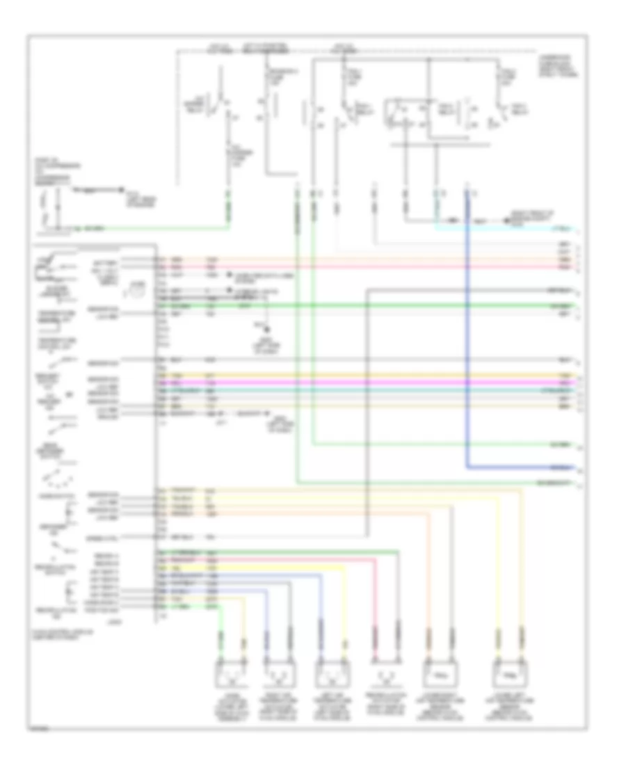
5.3L VIN C, Automatic A/C Wiring Diagram (1 of 2) for Buick Allure CXL 2009
List of elements for 5.3L VIN C, Automatic A/C Wiring Diagram (1 of 2) for Buick Allure CXL 2009:
- (part of a/c compressor) a/c compressor clutch
- (right front of engine compt) g100
- 87a
- A/c cmprsr fuse 10a
- A/c cmprsr relay
- A/c request ind
- A10
- A11
- A12
- Air temp a
- Air temp b
- Auto
- Battery
- Blower motor sw
- Class 2 serial
- Computer data lines system
- Defogger
- Emission 2 fuse 15a
- Fan 1 fuse 30a
- Fan 1 relay
- Fan 2 fuse 30a
- Fan 2 relay
- Fan 3 relay
- G112 (left rear of engine)
- G200 (left side of dash)
- G202 (left side of dash)
- Ground
- High
- Hot at all times
- Hot w/ pwr/trn relay energized
- Hvac control module (center of dash)
- Ign 1 volt
- Illum
- Ind
- Interior lights system
- J123
- J211
- J213
- Left air temperature actuator (left side of hvac module)
- Logic
- Low
- Low ref
- Lower left air temperature sensor (behind hvac control module)
- Lower right air temperature sensor (behind hvac control module)
- Mode actuator (lower left side of hvac assembly)
- Mode door a
- Mode switch
- Off
- Pnk
- Position sig
- Rear defogger switch
- Recirc a
- Recirc b
- Recirculation
- Recirculation actuator (right side of hvac module)
- Recirculation switch
- Request switch a/c
- Right air temperature actuator (right side of hvac module)
- Sensor sig
- Speed ctrl
- Tan
- Temperature control sw
- Underhood fuse block (right front strut tower)
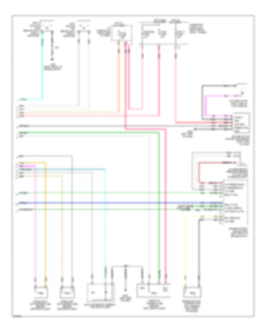
5.3L VIN C, Automatic A/C Wiring Diagram (2 of 2) for Buick Allure CXL 2009
List of elements for 5.3L VIN C, Automatic A/C Wiring Diagram (2 of 2) for Buick Allure CXL 2009:
- 5v reference 2
- A/c comp clutch
- A/c press signal
- A/c refrigerant pressure sensor (on left side of engine compt)
- Batt 4 fuse 30a
- Battery
- Blower motor (right side of hvac module)
- Blower motor control processor (right side of dash)
- Class 2 serial
- Compass fuse 10a
- Computer data lines system
- D11
- Ect sens sig
- Engine control module (ecm) (left front of engine compt)
- Engine coolant temperature (ect) sensor (left front of engine)
- G100 (right front of engine compt)
- G200 (left side of dash)
- G202 (left side of dash)
- Gnd
- Hot at all times
- Hot in run or start
- Hvac fuse 10a
- I/p fuse block (right side of dash)
- Ign 1 volt
- Inside air temperature sensor (left side of dash)
- J123
- J211
- Left cooling fan (behind left side of radiator)
- Low ref
- Pnk
- Radiator)
- Red
- Relay ctrl
- Right cooling fan (behind right side of b
- Speed ctrl
- Sunload sensor assembly (center of dash)
- Tan
- Underhood fuse block (right front strut tower)
- Upper left air temperature sensor (center of dash)
- Upper right air temperature sensor (center of dash)
5.3L VIN C, Compressor Wiring Diagram for Buick Allure CXL 2009
List of elements for 5.3L VIN C, Compressor Wiring Diagram for Buick Allure CXL 2009:
- (part of a/c compressor) a/c compressor clutch
- 5v reference
- A/c cmprsr fuse 10a
- A/c cmprsr relay
- A/c comp clutch
- A/c press signal
- A/c refrigerant pressure sensor (on left side of engine compt)
- A/c request ind
- A/c request switch
- Battery
- Class 2 serial
- Computer data lines system
- Emission 2 fuse 15a
- Engine control module (ecm) (left front of engine compt)
- G112 (left rear of engine)
- G202 (left side of dash)
- Ground
- Hot at all times
- Hot in run or start
- Hot w/ pwr/ trn relay energized
- Hvac control module (center of dash)
- Hvac fuse 10a
- I/p fuse block (right side of dash)
- Ignition 1
- J211
- Logic
- Low ref
- Pnk
- Underhood fuse block (right front strut tower)