AIR CONDITIONING
Compressor Wiring Diagram for Buick Century 2003

List of elements for Compressor Wiring Diagram for Buick Century 2003:
- (i/p harn, 18 cm from radio breakout)
- (i/p harn, right side of steering column, 19 cm from radio breakout)
- (lower left front of engine) g113
- (w/ auto a/c)
- (w/ manual a/c)
- 5 volt ref
- A/c clu diode
- A/c clutch fuse 23 10a
- A/c clutch relay 15
- A/c compressor clutch
- A/c press signal
- A/c refrigerent pressure sensor (left front strut tower, on a/c liquid line)
- A/c request
- Auto a/c
- Battery
- C11
- C12
- Class 2 ser data
- Clutch request
- Clutch rly ctrl
- D12
- Engine controls system
- G200 (behind right side of dash)
- Ground
- Hot at all times
- Hot in run
- Hvac control module
- Hvac fuse 10a
- I/p fuse block (behind right side of dash)
- Ign main relay (closed in run or start)
- Ignition
- Low ref
- Manual a/c
- Powertrain control module (left front side of engine compt, in air cleaner assembly)
- Rdo, hvac, rfa clstr, cel tel fuse 10a
- S105 (engine harn, front of engine compt, 4 cm from c105 breakout)
- S167 (engine harn, 4 cm from pcm breakout)
- S202
- S230
- S233 (i/p harn, behind center of dash, 4 cm from radio breakout)
- Serial data
- Sp205 (behind data link connector)
- Underhood fuse block (right side of engine compt)
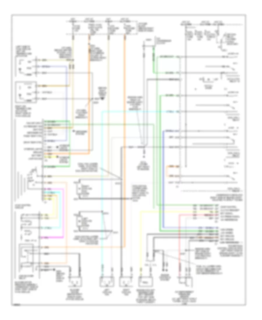
Manual A/C Wiring Diagram for Buick Century 2003
List of elements for Manual A/C Wiring Diagram for Buick Century 2003:
- (behind right side of dash) g200
- (cool fan jumper harn, 19 cm from right conn to cooling fan motor)
- (cooling fan jumper harn, 19.5 cm from right conn to cooling fan motor)
- (cooling fan jumper harn, 20 cm from left conn to cooling fan motor)
- (engine harn, front of engine compt, 4 cm from c105 breakout)
- (engine harn, left side of engine compt, 4 cm from pcm breakout)
- (fuel inj jumper harn, midway between fuel inj no 3 breakout & map sensor breakout)
- (i/p harn, 18 cm from radio breakout)
- (i/p harn, behind center of dash, 4 cm from radio breakout)
- (left side of hvac module) left air temperature actuator
- (top left side of engine, below throttle body)
- +5v reference
- 3.1l
- 3.8l
- A/c compressor clutch
- A/c clu diode
- A/c clutch fuse 23 10a
- A/c clutch relay 15
- A/c press signal
- A/c refrigerent pressure sensor (at left front strut tower, on a/c liquid line)
- A/c request sig
- A10
- A11
- Battery
- Blower motor (behind right side of dash, in hvac module)
- Blower motor resistor assembly (under right side of dash, right side of hvac module)
- C11
- Clutch request
- Comp control
- Cool fan 1 fuse 15a
- Cool fan 2 fuse 15a
- Cool fan 1 relay
- Cool fan 2 relay
- Cool fan 3 relay
- Defogger on
- Defogger system
- Drvr temp ctrl
- E10
- Ect ground
- Ect signal
- Engine controls system
- Engine coolant temperature (ect) sensor
- F12
- Fan off input
- G113 (lower
- G200 (behind right side of dash)
- Gnd
- Ground
- High blower fuse 30a
- High blower relay
- High speed
- Hot at all times
- Hot in run
- Hvac control module
- Hvac fuse 10a
- I/p fuse block (behind right side of dash)
- Ign
- Ign main relay (closed in run or start)
- Ignition
- Interior lights
- Interior lights system
- Lamp dim sig
- Left cooling fan
- Left cooling fan diode (3.1l)
- Left front of engine)
- Low blower fuse 20a
- Low reference
- Low speed
- Nca
- Nca nca
- Off
- Pass temp ctrl
- Pos
- Powertrain control module (pcm) (left front side of engine compt, in air cleaner assembly)
- Rdo, hvac, rfa clstr, cel tel fuse 10a
- Right air temperature actuator (right side of hvac module)
- Right cooling fan
- Right cooling fan diode (3.1l)
- S101
- S102
- S103
- S104
- S105
- S121
- S167
- S230
- S233
- Tan
- Underhood fuse block (right side of engine compt, mounted to strut tower)