AIR CONDITIONING
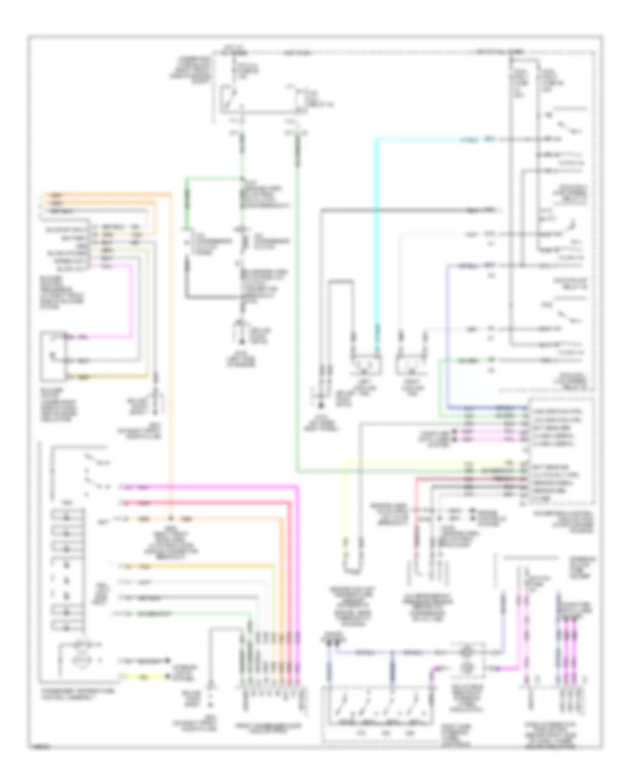
Automatic A/C Wiring Diagram (1 of 2) for Buick LeSabre Custom 2003

List of elements for Automatic A/C Wiring Diagram (1 of 2) for Buick LeSabre Custom 2003:
- (hvac harn, 23.5 cm from c204 breakout)
- (hvac harn, 30 cm from c204 breakout) s221
- (hvac harn, 36.5 cm from c204 break- out)
- (i/p harn, 13 cm from sunload sensor assembly breakout)
- (i/p harn, 13.5 cm from hvac breakout)
- (i/p harn, 6.5 cm from sunload sensor assembly breakout)
- (i/p harn, 6.5 cm outside from radio breakout)
- (on right front door pillar)
- 5v ref
- A10
- A11
- A12
- Air temperature actuator (left) (on left side of hvac module)
- Air temperature actuator (right) (on right side of hvac module)
- Air temperature sensor (inside) (on dash, right of steering column)
- Air temperature sensor (lower left) (behind left dash air discharge vent)
- Air temperature sensor (lower right) (behind right dash air discharge vent)
- Air temperature sensor (outside) (on hood latch support)
- Air temperature sensor (upper left) (behind left dash air discharge vent)
- Air temperature sensor (upper right) (behind right dash air discharge vent)
- Amb air temp sig
- Amb light sens
- Backlight lamps ctrl
- Battery
- Blwr sp ctrl
- C1 a1
- C11
- C12
- C13
- C3 a7
- C3 d12
- Class 2 serial
- Clock sig
- Computer data lines system
- D11
- D16
- Driver solar sig
- G100 (left side of engine)
- G201
- Grd
- Ground
- Hot at all times
- Hot in on
- Hvac (batt) fuse 37 10a
- Hvac blo fuse 2 30a
- Hvac control module
- Hvac fuse 33 10a
- Ign 3 fuse 34 10a
- Ign 3 volt
- In air temp sig
- Instrument panel integration module (ipm) (behind left side of dash)
- Interior lights system
- Lft air door sig
- Lft temp dr ctrl
- Low ref
- Lower lft temp sig
- Lower rt temp sig
- Mod sig
- Mode actuator (on left side of hvac module)
- Mode door ctrl
- Mode dr pos sens
- Pass mdl fuse 25 10a
- Pass solar sig
- Rear fuse block (under left rear seat)
- Recirc door ctrl
- Recirc door sig
- Recirculation actuator (under right side of dash, right of blower motor)
- Rt air door sig
- Rt temp dr ctrl
- S204
- S205
- S208
- S222
- S253
- Solid state
- Splice pack sp100
- Splice pack sp201
- Sunload sensor assembly (on top center of dash)
- Tan
- Upper lh temp sig
- Upper rt temp sig
Automatic A/C Wiring Diagram (2 of 2) for Buick LeSabre Custom 2003
List of elements for Automatic A/C Wiring Diagram (2 of 2) for Buick LeSabre Custom 2003:
- (engine harn, 6.5 cm from iac valve breakout)
- 5v ref
- A/c clu fuse 26 15a
- A/c clu relay 32
- A/c compressor clutch
- A/c compressor clutch diode
- A/c refrigerant pressure sensor (behind a/c compressor, on a/c line)
- A10
- A11
- A12
- B10
- B11
- Bat
- Battery
- Blower control processor (at right front side of blower motor)
- Blower motor (under right side of dash, above sound insulator)
- Blwr mtr grd
- Blwr sp input
- Blwr volt
- C10
- C11
- Class 2 serial
- Clutch rly ctrl
- Cntl sig
- Computer data lines system
- Cool fan 1 fuse 30a
- Cool fan 2 fuse 46 30a
- Coolfan 1 (low speed) relay 40
- Coolfan 2 (high speed) relay 37
- Coolfan s/p relay 39
- D10
- Dash integration module (dim) (behind right side of dash, under sound insulator)
- E10
- E11
- Ect sens grd
- Ect sens sig
- Engine controls system
- Engine coolant temperature sensor (on rear of
- Engine, near thermostat housing)
- F11
- Front passenger door module (fpdm)
- G10
- G100 (left side of engine)
- G103 (on inner body panel)
- G11
- G201 (on right front door pillar)
- Grd
- Ground
- High spd fan ctrl
- Hot at all times
- Hot in on
- Inflatable restraint steering wheel module coil
- Interior lights system
- Left cooling fan
- Low spd fan ctrl
- Passenger temperature control assembly
- Pdm low side input
- Pnk
- Powertrain control module (pcm) (in air cleaner housing)
- Right cooling fan
- Right side steering wheel controls
- S106
- S602 (right front door harn, 10 cm from door module connector breakout)
- Sensor grd
- Sensor signal
- Sound systems
- Speed cntl
- Splice pack sp100
- Splice pack sp103
- Splice pack sp201
- Steering column fuse holder
- Sw grd
- Sw1
- Sw2
- Sw3
- Sw4
- Switch fuse 2a
- T10
- T11
- Tan
- Underhood fuse block (right front side of engine compt)
- V10
- V11
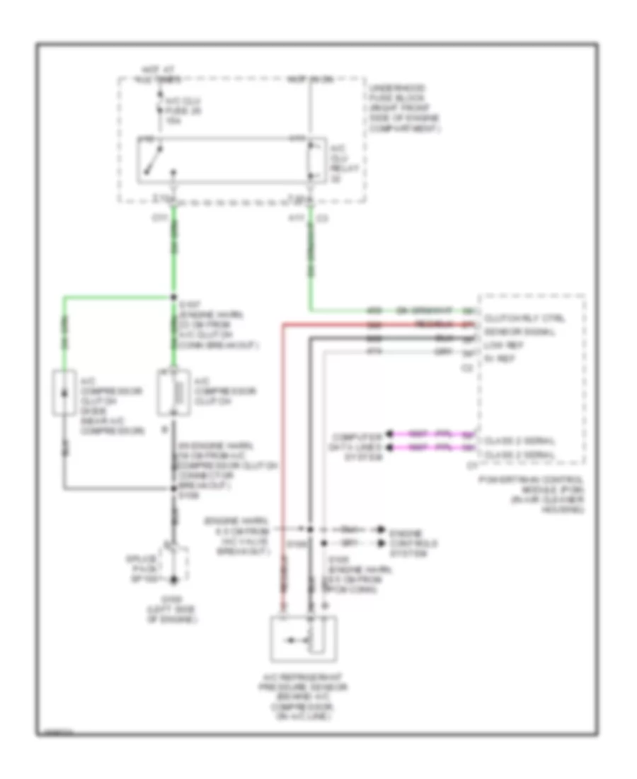
Compressor Wiring Diagram for Buick LeSabre Custom 2003
List of elements for Compressor Wiring Diagram for Buick LeSabre Custom 2003:
- (engine harn, 6.5 cm from iac valve breakout)
- (in engine harn, 18 cm from a/c compressor clutch connector breakout) s108
- 5v ref
- A/c clu fuse 26 15a
- A/c clu relay
- A/c compressor clutch
- A/c compressor clutch diode (near a/c compressor)
- A/c refrigerant pressure sensor (behind a/c compressor, on a/c line)
- Class 2 serial
- Clutch rly ctrl
- Computer data lines system
- Engine controls system
- G100 (left side of engine)
- Hot at all times
- Hot in on
- Low ref
- Powertrain control module (pcm) (in air cleaner housing)
- S106
- Sensor signal
- Splice pack sp100
- T10
- T11
- Underhood fuse block (right front side of engine compartment)
- V10
- V11
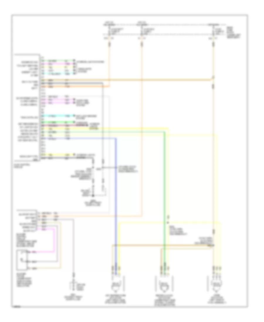
Manual A/C Wiring Diagram (1 of 2) for Buick LeSabre Custom 2003
List of elements for Manual A/C Wiring Diagram (1 of 2) for Buick LeSabre Custom 2003:
- (hvac harn, 30 cm from c204 breakout) s221
- (i/p harn, 6.5 cm outside from radio breakout)
- 5v ref
- A10
- A11
- A12
- A13
- A14
- A15
- A16
- Air temp dr ctrl
- Air temperature actuator (left front side of blower motor)
- Ambient light
- Anti-lock brakes system
- B10
- B11
- B12
- B13
- B14
- B15
- B16
- Backlight ctrl
- Batt
- Battery
- Blower control module (under right side of dash, above blower motor)
- Blower motor (under right side of dash, above sound insulator)
- Blwr mtr grd
- Blwr sp input
- Blwr speed cntrl
- Blwr volt
- C1 a10
- Class 2 serial
- Computer data lines system
- D12
- Dimmer sw sig
- G200 (on left front door pillar)
- G201 (on right front door pillar)
- Grd
- Headlights system
- Hot at all times
- Hot in on
- Hvac batt fuse 37 10a
- Hvac blo fuse 2 30a
- Hvac control module
- Hvac fuse 33 10a
- Ign 3 voltage
- Int lamp sw sig
- Interior lights system
- Key reminder sw
- Low ref
- Mode actuator (left side of hvac assembly)
- Motor low ref
- Rear fuse block (under left rear seat)
- Recirc dr mtr
- Recirculation actuator (under right side of dash, to right of blower motor)
- S208 (i/p harn, 13 cm from sunload sensor assembly breakout)
- S222 (hvac harn, 23.5 cm from c204 breakout)
- S253
- Solid state
- Speed cntl
- Splice pack sp200
- Splice pack sp201
- Trac cntrl sw
- Twilight sentinel
- Warnings system
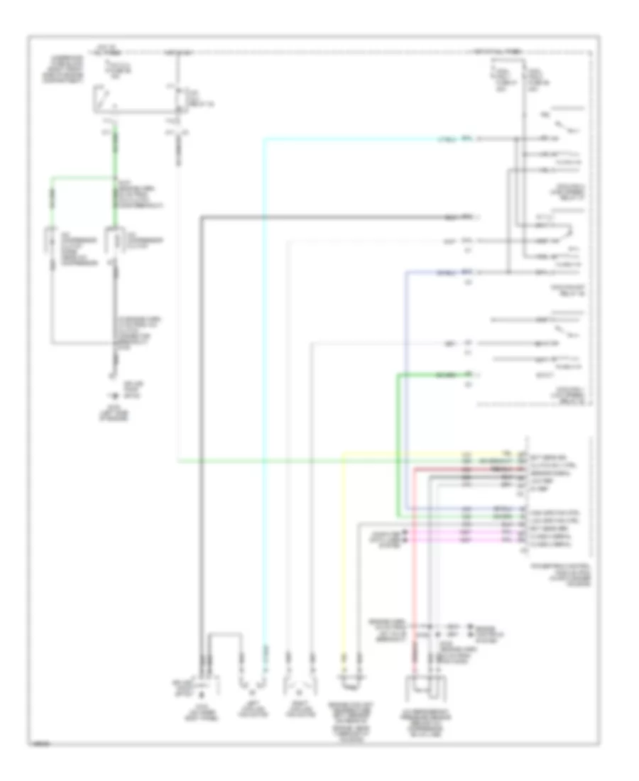
Manual A/C Wiring Diagram (2 of 2) for Buick LeSabre Custom 2003
List of elements for Manual A/C Wiring Diagram (2 of 2) for Buick LeSabre Custom 2003:
- (engine harn, 6.5 cm from iac valve breakout)
- (in engine harn, 18 cm from a/c clutch connector breakout) s108
- 5v ref
- A/c clu fuse 26 15a
- A/c clu relay 32
- A/c compressor clutch
- A/c compressor clutch diode (near a/c compressor)
- A/c refrigerant pressure sensor (behind a/c compressor, on a/c line)
- A10
- A11
- B10
- B11
- C10
- C11
- Class 2 serial
- Clutch rly ctrl
- Computer data lines system
- Cool fan 1 fuse 47 30a
- Cool fan 2 fuse 46 30a
- Coolfan 1 (low speed) relay 40
- Coolfan 2 (high speed) relay 37
- Coolfan s/p relay 39
- D10
- E10
- E11
- Ect sens grd
- Ect sens sig
- Engine controls system
- Engine coolant temperature (ect) sensor (on rear of
- Engine, near thermostat housing)
- F11
- G10
- G100 (left side of engine)
- G103 (on inner body panel)
- G11
- High spd fan ctrl
- Hot at all times
- Hot in on
- Left cooling fan motor
- Low ref
- Low spd fan ctrl
- Powertrain control module (pcm) (in air cleaner housing)
- Right cooling fan motor
- S106
- Sensor signal
- Splice pack sp100
- Splice pack sp103
- T10
- T11
- Underhood fuse block (right front side of engine compartment)
- V10
- V11