AIR CONDITIONING
Automatic A/C Wiring Diagram (1 of 2) for Buick Lucerne CX 2007

List of elements for Automatic A/C Wiring Diagram (1 of 2) for Buick Lucerne CX 2007:
- (approximately 7 cm (3 in) from branch for hazard lamp switch) s202
- (in engine harness, approximately 7 cm (3 in) from branch for throttle body assembly)
- (in i/p harness, approximately 41 cm (16 in) from branch for hazard lamp switch) s210
- (lower left rear of engine)
- (under driver's seat) g300
- (under right front passenger's seat) g304
- 3.8l
- 4.6l
- 5 volt ref
- A/c compressor clutch (on a/c compressor)
- Air temp motor ctrl
- Ambient air temp sens sig
- Ambient air temperature sensor (on center front of engine compt, on hood latch brace)
- Ambient light sensor sig
- Backlight lamp ctrl
- Batt pos vol
- Batt pos volt
- Blower motor (behind right side of dash)
- Blower motor control module (near blower motor)
- Body control module (bcm) (right of glove box)
- Cold
- Computer data lines system
- Defogger system
- Drv air temp dr ctrl a
- Drv air temp dr ctrl b
- Drv air temp dr pos sig
- Engine coolant hot
- Evap low temp sens sig
- Evaporator temperature sensor (left of blower motor)
- G112
- G115
- G300 (under driver's seat)
- Gmlan serial data
- Gnd
- Hot
- Hot at all times
- Hvac blwr fuse 40a
- Hvac control module
- I/p harn mdl fuse 10a
- Ign 1 volt
- Inside air temp sens sig
- Inside air temperature sensor (under left side of dash, left of steering column)
- Interior lights system
- L sunload sens sig
- Led dimming sig
- Left sunload sensor signal
- Logic
- Low ref
- Low reference
- Low speed gmlan serial data
- Lower mode dr ctrl b
- Lower mode dr pos sig
- Message center
- Message req
- Mode door control a
- Pass air temp dr ctrl b
- Pass air temp dr pos
- Pnk
- Power distribution system
- R sunload sens sig
- Radio
- Rear defog rly ctrl
- Rear fuse block (below left side of rear seat)
- Recir dr ctrl a
- Recir dr ctrl b
- Recir valve sol sig
- Recirculation actuator (behind right side of dash, right of blower motor)
- Right sunload sensor signal
- S106
- S200 (approximately 6 cm (2 in) from branch for hvac module)
- S203 (approximately 36 cm (14 in) from breakout for hvac module)
- S387
- Solid state
- Speed ctrl
- Sunload twilight sensor (top center of dash)
- Tan
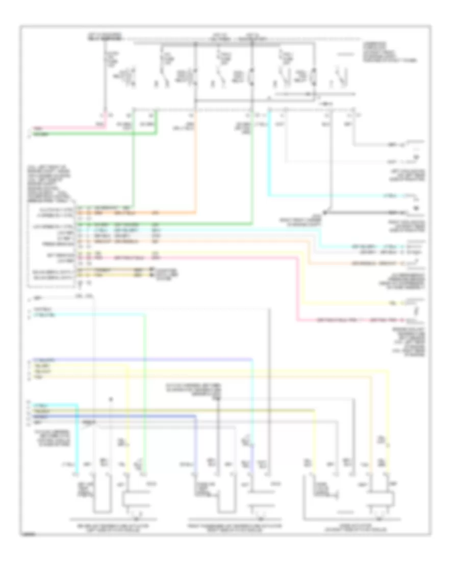
Automatic A/C Wiring Diagram (2 of 2) for Buick Lucerne CX 2007
List of elements for Automatic A/C Wiring Diagram (2 of 2) for Buick Lucerne CX 2007:
- (3.8l)
- (3.8l: left front of engine compt, inside air cleaner housing) (4.6l: left side of engine compt) engine control module (ecm) powertrain control module (pcm)
- (4.6l)
- (in hvac harness, between evaporator temperature sensor & c202) s227
- (in hvac harness, between hvac control module & mode motors)
- (or tan)
- 3.8l
- 4.6l
- 5v ref 1
- A/c fuse 10a
- A/c refrigerant pressure sensor (near a/c compressor, on hose assembly)
- A/c relay
- Clutch rly ctrl
- Cold
- Computer data lines system
- Cool/ fan 1 relay
- Cool/ fan 2 relay
- Cool/ fan relay
- Def
- Driver air temperature actuator (left side of hvac module)
- Dry air temp signal
- Ect sens sig
- Engine coolant temperature (ect) sensor (3.8l: left rear of engine) (4.6l: right rear of engine)
- Fan 1 fuse 30a
- Fan 2 fuse 30a
- Front passenger air temperature actuator (right side of hvac module)
- G104 (right front corner of engine compt)
- Gmlan serial data +
- Gmlan serial data -
- Hi speed rly ctrl
- Hot
- Hot at all times
- Hot in run or start
- Hot w/ run/crnk relay energized
- Hvac/ ipc fuse 10a
- Left cooling fan (on left rear side of radiator)
- Low ref
- Low speed rly ctrl
- Mode actuator (on right side of hvac module)
- Mode valve signal
- Pass air temp signal
- Pnk
- Press sens sig
- Right cooling fan (on right rear side of radiator)
- S226
- Tan
- Underhood fuse block (on right front of engine compt, forward of strut tower)
- Vent
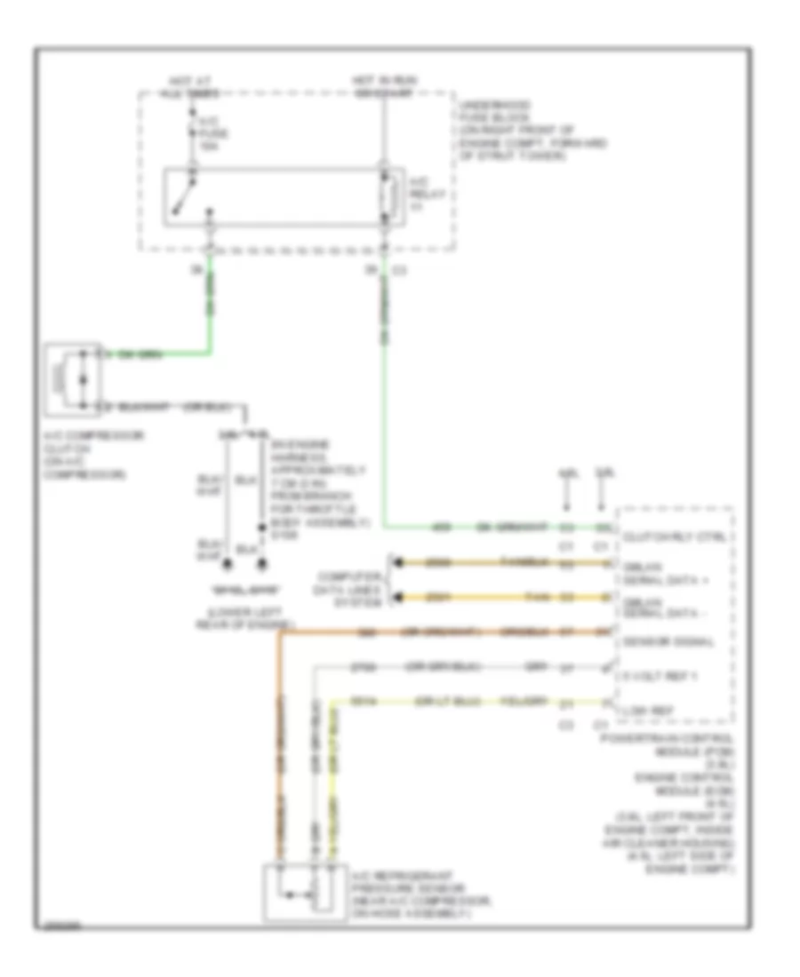
Compressor Wiring Diagram for Buick Lucerne CX 2007
List of elements for Compressor Wiring Diagram for Buick Lucerne CX 2007:
- (in engine harness, approximately 7 cm (3 in) from branch for throttle body assembly) s106
- (lower left rear of engine)
- 3.8l
- 4.6l
- 4.6l 3.8l
- 5 volt ref 1
- A/c compressor clutch (on a/c compressor)
- A/c fuse 10a
- A/c refrigerant pressure sensor (near a/c compressor, on hose assembly)
- A/c relay
- Clutch rly ctrl
- Computer data lines system
- G112
- G115
- Gmlan serial data +
- Gmlan serial data -
- Hot at all times
- Hot in run or start
- Low ref
- Powertrain control module (pcm) (3.8l) engine control module (ecm) (4.6l) (3.8l: left front of engine compt, inside air cleaner housing) (4.6l: left side of engine compt)
- Sensor signal
- Tan
- Underhood fuse block (on right front of engine compt, forward of strut tower)
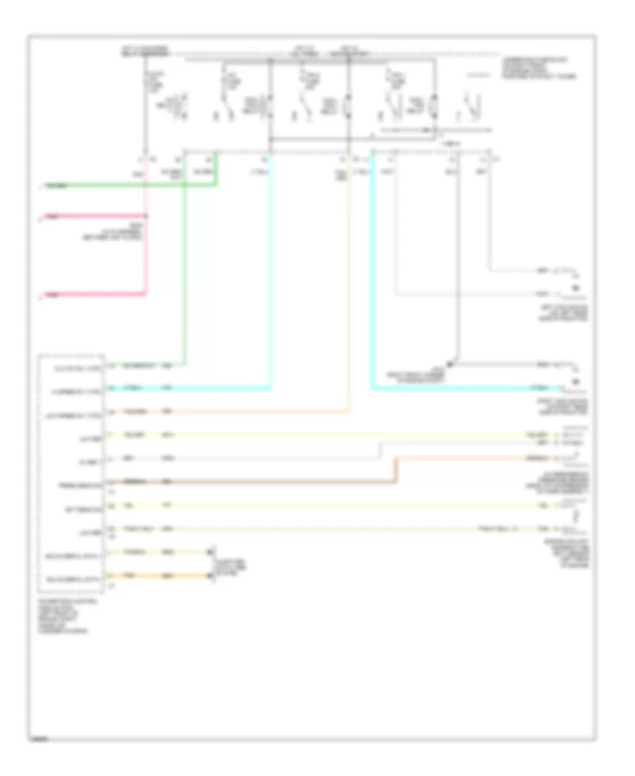
Manual A/C Wiring Diagram (1 of 2) for Buick Lucerne CX 2007
List of elements for Manual A/C Wiring Diagram (1 of 2) for Buick Lucerne CX 2007:
- (approximately 36 cm (14 in) from breakout for hvac module)
- (in hvac harness, between evaporator temperature sensor & c202)
- (in hvac harness, between hvac control module & mode motors)
- (in i/p harness, approximately 41 cm (16 in) from branch for hazard lamp switch) s210
- (under right front passenger's seat) g304
- 5 volt ref
- A/c compressor clutch (on a/c compressor)
- Air temp dr ctrl b
- Air temp dr pos sig
- Air temperature actuator (right side of hvac module)
- Ambient air temp sens sig
- Ambient air temperature sensor (on center front of engine compt, on hood latch brace)
- Backlight lamp ctrl
- Batt pos vol
- Batt pos volt
- Blower motor (behind right side of dash)
- Blower motor control module (near blower motor)
- Cold
- Computer data lines system
- Def
- Defogger system
- Driver air temp signal
- Drv air temp dr ctrl a
- Evap low temp sens sig
- Evap temperature sensor (left of blower motor)
- G112 (lower left rear of engine)
- G300 (under driver's seat)
- Gnd
- Hot
- Hot at all times
- Hvac blwr fuse
- Hvac control module
- I/p harn mdl fuse 10a
- Ign 1 volt
- Interior lights system
- Led dimming sig
- Logic
- Low mode dr pos sig
- Low ref
- Low speed gmlan serial data
- Lower mode dr ctrl b
- Mode actuator (on right side of hvac module)
- Mode dr ctrl a
- Mode valve signal
- Pnk
- Power distribution system
- Rear defog rly ctrl
- Rear fuse block (below left side of rear seat)
- Recir door a ctrl
- Recir door b ctrl
- Recirculation actuator (behind right side of dash, right of blower motor)
- S200 (approximately 6 cm (2 in) from branch for hvac module)
- S203
- S226
- S227
- S387
- Speed ctrl
- Tan
- Vent
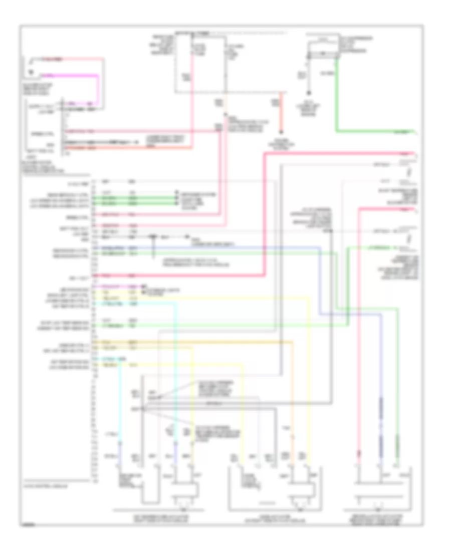
Manual A/C Wiring Diagram (2 of 2) for Buick Lucerne CX 2007
List of elements for Manual A/C Wiring Diagram (2 of 2) for Buick Lucerne CX 2007:
- 5v ref 1
- A/c fuse 10a
- A/c refrigerant pressure sensor (near a/c compressor, on hose assembly)
- A/c relay
- Clutch rly ctrl
- Computer data lines system
- Cool/ fan 1 relay
- Cool/ fan 2 relay
- Cool/ fan relay
- Ect sens sig
- Engine coolant temperature (ect) sensor (left rear of engine)
- Fan 1 fuse 30a
- Fan 2 fuse 30a
- G104 (right front corner of engine compt)
- Gmlan serial data +
- Gmlan serial data -
- Hi speed rly ctrl
- Hot at all times
- Hot in run or start
- Hot w/ run/crnk relay energized
- Hvac/ ipc fuse 10a
- Left cooling fan (on left rear side of radiator)
- Low ref
- Low speed rly ctrl
- Pnk
- Powertrain control module (pcm) (left front of engine compt, inside air cleaner housing)
- Press sens sig
- Right cooling fan (on right rear side of radiator)
- S229 (in ip harness, between c201 & c202)
- Tan
- Underhood fuse block (on right front of engine compt, forward of strut tower)