AIR CONDITIONING
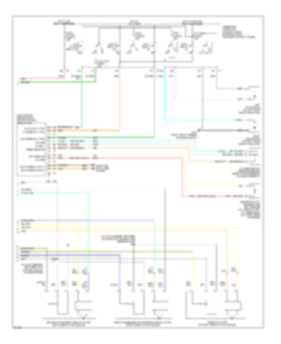
Automatic A/C Wiring Diagram (1 of 2) for Buick Lucerne CXL 2009

List of elements for Automatic A/C Wiring Diagram (1 of 2) for Buick Lucerne CXL 2009:
- (in i/p harness, approximately 41 cm (16 in) from branch for hazard lamp switch) j210
- (lower left rear of engine)
- (under driver's seat) g300
- (under right front passenger's seat) g304
- 3.9l
- 4.6l
- 5 volt ref
- A/c compressor clutch (on a/c compressor)
- Air temp motor ctrl
- Ambient air temp sens sig
- Ambient air temperature sensor (on center front of engine compt, on hood latch brace)
- Backlight lamp ctrl
- Batt pos vol
- Batt pos volt
- Blower motor (behind right side of dash)
- Blower motor control module (near blower motor)
- Body control module (bcm) (right of glove box)
- Computer data lines system
- Defogger system
- Driver information center (dic) display
- Drv air temp dr ctrl a
- Drv air temp dr ctrl b
- Drv air temp dr pos sig
- Evap low temp sens sig
- Evap temperature sensor (left of blower motor)
- G112
- G115
- G300 (under driver's seat)
- Gmlan serial data
- Gnd
- Hot at all times
- Hvac control module
- Ign 1 volt
- Inside air temp sens sig
- Inside air temperature sensor (under left side of dash, left of steering column)
- Instrument panel cluster (ipc)
- Interior lights system
- J106
- J200
- J202
- J203
- J250
- J387
- L sunload sens sig
- Led dimming sig
- Logic
- Low ref
- Low speed gmlan serial data
- Lower mode dr ctrl b
- Lower mode dr pos sig
- Mode door control a
- Mtr fuse 48 10a
- Pass air temp dr ctrl a
- Pass air temp dr ctrl b
- Pass air temp dr pos
- Passkey fuse 13 10a
- Pnk
- Power distribution system
- R sunload sens sig
- Rear defog rly ctrl
- Rear fuse block (below left side of rear seat)
- Recir dr ctrl a
- Recir dr ctrl b
- Recir valve sol sig
- Recirculation actuator (behind right side of dash, right of blower motor)
- Speed ctrl
- Sunload twilight sensor (top center of dash)
- Tan
- X4 b
Automatic A/C Wiring Diagram (2 of 2) for Buick Lucerne CXL 2009
List of elements for Automatic A/C Wiring Diagram (2 of 2) for Buick Lucerne CXL 2009:
- (in hvac harness, between evaporator temperature sensor & x202) j227
- (in hvac harness, between hvac control module & mode motors)
- (left side of engine compt) engine control module (ecm)
- (or tan)
- 3.9l
- 4.6l
- 5v ref 1
- 87a
- A/c cltch fuse 4 10a
- A/c cltch relay 34
- A/c refrigerant pressure sensor (near a/c compressor, on hose assembly)
- Clutch rly ctrl
- Computer data lines system
- Driver air temperature actuator (left side of hvac module)
- Ect sens sig
- Engine coolant temperature (ect) sensor (3.9l: rear of left cylinder bank) (4.6l: right rear of engine)
- Fan 1 fuse 27 30a
- Fan 1 relay
- Fan 2 fuse 26 30a
- Fan 2 relay
- Fan 3 relay
- Front passenger air temperature actuator (right side of hvac module)
- G104 (right front corner of engine compt)
- Gmlan serial data +
- Gmlan serial data -
- Hi speed rly ctrl
- Hot at all times
- Hot w/ ign relay energized
- Hot w/ pwr/trn relay energized
- Hvac/ ipc ign 1 fuse 10 10a
- J226
- Left cooling fan (on left rear side of radiator)
- Low ref
- Low speed rly ctrl
- Mode actuator (on right side of hvac module)
- Oxy snsr fuse 6 15a
- Pnk
- Press sens sig
- Right cooling fan (on right rear side of radiator)
- Tan
- Underhood fuse block (on right front of engine compt, forward of strut tower)
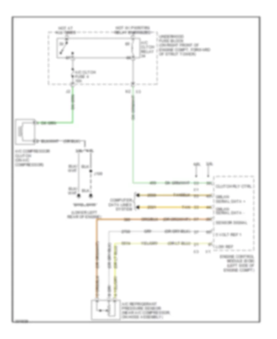
Compressor Wiring Diagram for Buick Lucerne CXL 2009
List of elements for Compressor Wiring Diagram for Buick Lucerne CXL 2009:
- (lower left rear of engine)
- 3.9l
- 4.6l
- 4.6l 3.9l
- 5 volt ref 1
- A/c cltch fuse 4 10a
- A/c cltch relay
- A/c compressor clutch (on a/c compressor)
- A/c refrigerant pressure sensor (near a/c compressor, on hose assembly)
- Clutch rly ctrl
- Computer data lines system
- Engine control module (ecm) (left side of engine compt)
- G112
- G115
- Gmlan serial data +
- Gmlan serial data -
- Hot at all times
- Hot w/ pwr/trn relay energized
- J106
- Low ref
- Sensor signal
- Tan
- Underhood fuse block (on right front of engine compt, forward of strut tower)
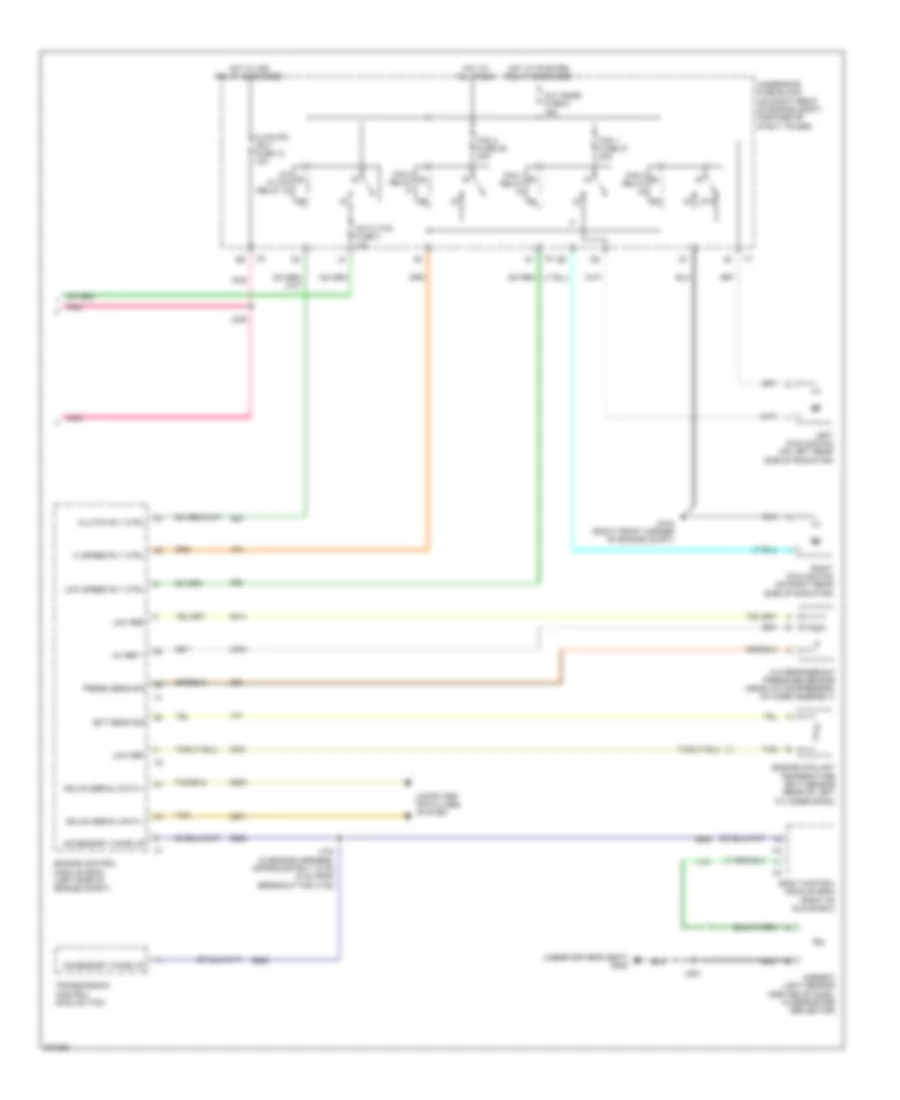
Manual A/C Wiring Diagram (1 of 2) for Buick Lucerne CXL 2009
List of elements for Manual A/C Wiring Diagram (1 of 2) for Buick Lucerne CXL 2009:
- (in hvac harness, between evaporator temperature sensor & x202)
- (in hvac harness, between hvac control module & mode motors)
- (in i/p harness, approximately 41 cm (16 in) from branch for hazard lamp switch) j210
- (under right front passenger's seat) g304
- 5 volt ref
- A/c compressor clutch (on a/c compressor)
- A/c high pres reur sw sig
- Air temp dr ctrl
- Air temp dr pos sig
- Air temperature actuator (right side of hvac module)
- Ambient air temp sens sig
- Ambient air temperature sensor (on center front of engine compt, on hood latch brace)
- Backlight lamp ctrl
- Batt pos vol
- Batt pos volt
- Blower fuse 49 40a
- Blower motor (behind right side of dash)
- Blower motor control module (near blower motor)
- Computer data lines system
- Defogger system
- Evap low temp sens sig
- Evap temperature sensor (left of blower motor)
- G112 (lower left rear of engine)
- G300 (under driver's seat)
- Gnd
- Hot at all times
- Hvac control module
- Ign 1 volt
- Interior lights system
- J200
- J203
- J226
- J227
- J387
- Led dimming sig
- Logic
- Low mode dr pos sig
- Low ref
- Low speed gmlan serial data
- Lower mode dr ctrl b
- Mode actuator (on right side of hvac module)
- Mode dr ctrl a
- Passkey fuse 13 10a
- Pnk
- Power distribution system
- Rear defog rly ctrl
- Rear fuse block (below left side of rear seat)
- Recirculation actuator (behind right side of dash, right of blower motor)
- Sensor signal
- Speed ctrl
- Tan
- X4 b
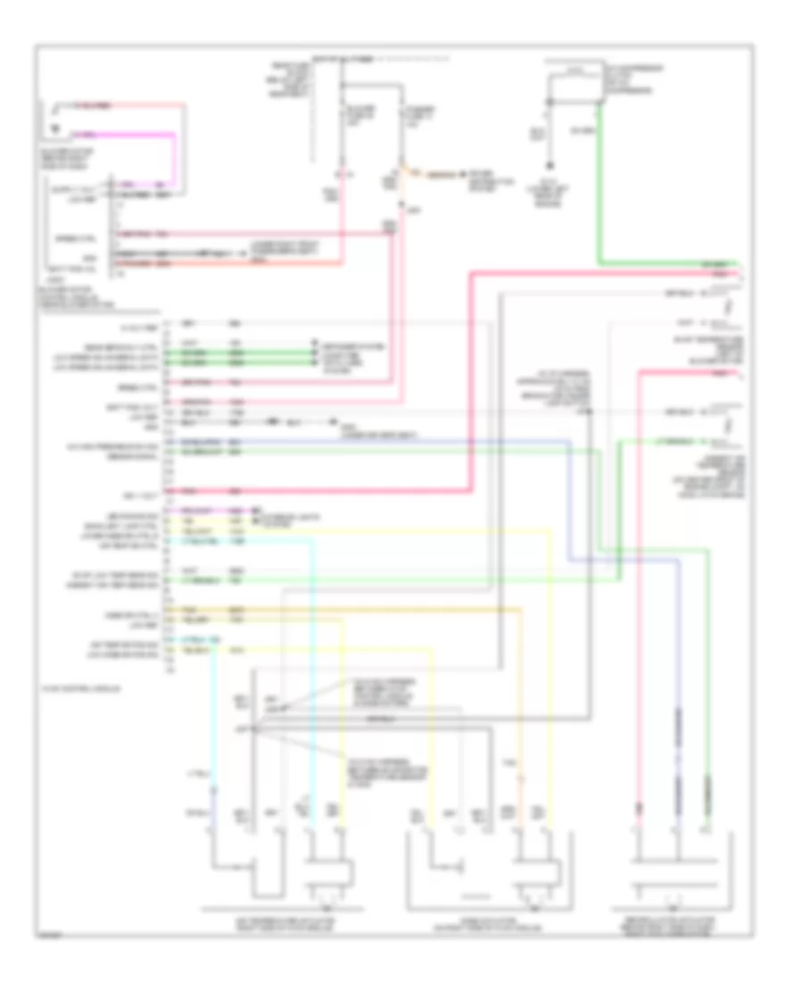
Manual A/C Wiring Diagram (2 of 2) for Buick Lucerne CXL 2009
List of elements for Manual A/C Wiring Diagram (2 of 2) for Buick Lucerne CXL 2009:
- (under driver's seat) g300
- 5v ref 1
- 87a
- A/c cltch fuse 4 10a
- A/c cltch relay 34
- A/c refrigerant pressure sensor (near a/c compressor, on hose assembly)
- Accessory wake up
- Ambient light sensor (center of dash, in defroster deflector)
- Body control module (bcm) (right of glove box)
- Clutch rly ctrl
- Computer data lines system
- Ect sens sig
- Engine control module (ecm) (left side of engine compt)
- Engine coolant temperature (ect) sensor (rear of left cylinder bank)
- Fan 1 fuse 27 30a
- Fan 1 relay
- Fan 2 fuse 26 30a
- Fan 2 relay
- Fan 3 relay
- G104 (right front corner of engine compt)
- Gmlan serial data +
- Gmlan serial data -
- Hi speed rly ctrl
- Hot at all times
- Hot w/ ign relay energized
- Hot w/ pwr/trn relay energized
- Hvac/ipc ign 1 fuse 10 10a
- J104 (in engine harness, approximately 13 cm (5 in) from breakout for x138)
- J203
- J229
- Left cooling fan (on left rear side of radiator)
- Low ref
- Low speed rly ctrl
- Oxy snsr fuse 6 15a
- Pnk
- Press sens sig
- Right cooling fan (on right rear side of radiator)
- Tan
- Transmission control module (tcm)
- Underhood fuse block (on right front of engine compt, forward of strut tower)