AIR CONDITIONING
Automatic A/C Wiring Diagram (1 of 3) for Buick Park Avenue 2002

List of elements for Automatic A/C Wiring Diagram (1 of 3) for Buick Park Avenue 2002:
- (dash harn, 44 cm from hvac ctrl assembly)
- 5 volt ref
- A10
- A11
- A12
- Amb temp sig
- Ambient air temperature sensor (center front of engine compt)
- B10
- B11
- B12
- Bat pos volt
- Blower spd ctrl
- C10
- C11
- C12
- C13
- C14
- C15
- C16
- Class 2 serial
- Clock sig
- Computer data lines system
- Cstr/ sbm fuse 10a
- D10
- D11
- D12
- D13
- D14
- D15
- D16
- Data sig
- G202 (left kick panel)
- Grd
- Ground
- Hot at all times
- Hot in run or start
- Hvac control module
- Hvac fuse 10a
- I/p fuse block (behind glove box)
- Ign 3 volt
- Inside air temperature sensor (under left side of dash, near left center a/c vent)
- Inside temp sig
- Instrument panel integration module (ipm) (behind right side of dash)
- Interior lights system
- Lamp volt
- Lft dr pos sig
- Lft solar sens
- Lft temp dr ctrl
- Ll temp sig
- Low ref
- Low rt temp sig
- Lower left air temperature sensor (left side of dash, above sound insulator)
- Lower right air temperature sensor (right side of dash, above sound insulator)
- Mode door ctrl
- Mode dr pos sig
- Pass solar sens
- Recirc door ctrl
- Red
- Right air temperature switch assembly
- Rt dr pos sig
- Rt temp dr ctrl
- Rt temp sig
- S213
- S213 (dash harn, 44 cm from hvac control assembly)
- S214 (dash harn, behind right side of dash)
- Serial data
- Sun load sensor (left) (on left of dash)
- Sun load sensor (right) (on right of dash)
- Tan
- Up lft temp sig
- Up rt temp sig
- Upper air temperature sensor (left) (left side of dash, near a/c vent)
- Upper air temperature sensor (right) (right side of dash, near a/c vent)
- Vf dim sig
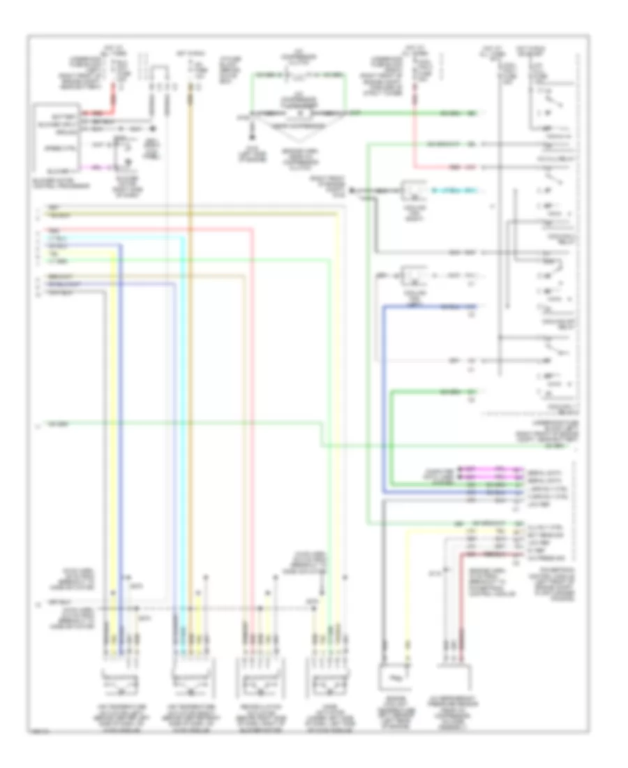
Automatic A/C Wiring Diagram (2 of 3) for Buick Park Avenue 2002
List of elements for Automatic A/C Wiring Diagram (2 of 3) for Buick Park Avenue 2002:
- (engine harn, 15 cm from breakout to powertrain control module)
- (engine harn, near a/c compressor clutch)
- (hvac harn, 29 cm from breakout to mode actuator)
- (hvac harn, 33.5 cm from breakout to mode actuator)
- (hvac harn, 50.5 cm from breakout to mode actuator)
- (near compressor)
- (right front of engine compt) g105
- 5v ref
- 87a
- A/c clu fuse 10a
- A/c clu relay
- A/c compressor clutch
- A/c compressor clutch diode
- A/c fuse 10a
- A/c press sig
- A/c refrigerant pressure sensor (near a/c compressor, on hose assembly)
- A10
- Air temperature actuator (left) (behind center left side of dash, on hvac module)
- Air temperature actuator (right) (behind center right side of dash, on hvac module)
- Battery
- Blo mot fuse 30a
- Blower input
- Blower motor (right side of dash)
- Blower motor control processor
- Blower v+
- Clu rly ctrl
- Computer data lines system
- Cool fan 1 fuse 30a
- Cool fan 2 fuse 30a
- Coolfan 1 relay
- Coolfan 2 relay
- Coolfan s/p relay
- Cooling fan (left)
- Cooling fan (right)
- D11
- E10
- Ect sens sig
- Engine coolant temperature (ect) sensor (left rear of engine)
- F11
- G102 (left side
- G201 (right kick panel)
- Ground
- H spd rly ctrl
- Hot at all times
- Hot in run
- Hot in run or start
- I/p fuse block (behind glove box)
- L spd rly ctrl
- Low ref
- Mode actuator (under left side of dash, left side of hvac module)
- Nca
- Of engine)
- Powertrain control module (left front of engine compt, in air cleaner housing)
- Recirculation actuator (behind right side of dash, right of blower motor)
- Red
- S106
- S107
- S115
- S208
- S274
- S275
- S278
- Serial data
- Solid state
- Speed ctrl
- Underhood fuse block (left) (right front of engine compt, near battery)
- Underhood fuse block (right) (right front of engine compt, forward of strut tower)
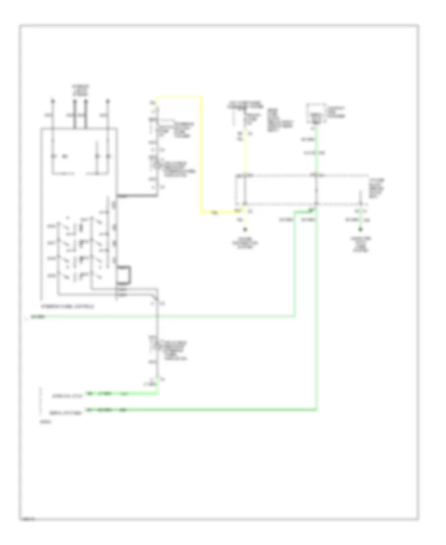
Automatic A/C Wiring Diagram (3 of 3) for Buick Park Avenue 2002
List of elements for Automatic A/C Wiring Diagram (3 of 3) for Buick Park Avenue 2002:
- B12
- C1 f5
- Compact disc changer
- Computer data lines system
- F8 c4
- Hot in retained accessory power
- I/p fuse block (behind glove box)
- Inflatable restraint steering wheel module coil
- Interior lights system
- Nca
- Power distribution system
- Radio
- Rdo/ph fuse 5a
- Rear fuse block (below right side of rear seat)
- Serial data e&c
- Steering column fuse holder
- Steering wheel controls
- Strg whl ctlr
- Sw1
- Sw2
- Sw3
- Sw4
- Sw5
- Sw6
- Sw7
- Sw8
- Switch fuse 2a
- W/u1s
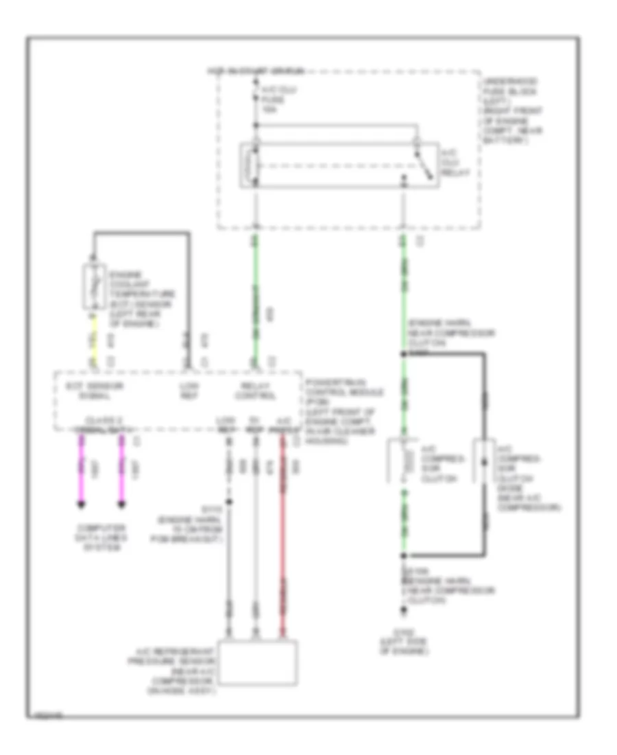
Compressor Wiring Diagram for Buick Park Avenue 2002
List of elements for Compressor Wiring Diagram for Buick Park Avenue 2002:
- (engine harn, near compressor clutch)
- (engine harn, near compressor clutch) s107
- 5v ref
- A/c clu relay
- A/c clu fuse 10a
- A/c compres- sor clutch
- A/c compres- sor clutch diode (near a/c compressor)
- A/c press
- A/c refrigerant pressure sensor (near a/c compressor, on hose assy)
- Class 2 serial data
- Computer data lines system
- Ect sensor signal
- Engine coolant temperature (ect) sensor (left rear of engine)
- G102 (left side of engine)
- Hot in start or run
- Low ref
- Nca
- Powertrain control module (pcm) (left front of engine compt, in air cleaner housing)
- Relay control
- S115 (engine harn, 15 cm from pcm breakout)
- Underhood fuse block (left) (right front of engine compt, near battery)