AIR CONDITIONING
A/C Wiring Diagram, Auto A/C (1 of 2) for Buick Park Avenue Ultra 1995

List of elements for A/C Wiring Diagram, Auto A/C (1 of 2) for Buick Park Avenue Ultra 1995:
- (top left side of i/p)
- (top right side of i/p)
- +5v
- A/c compres- sor clutch
- A/c compres- sor clutch diode
- A/c compressor control relay (center rear of engine compartment)
- A/c request
- Ambient temperature sensor (center front of vehicle)
- Battery
- Blower control
- Blower control module (center rear of engine compartment)
- Blower feedback
- Blower motor
- C 1995 vftc
- Computer data lines system
- Data line
- Data link connector (below left side of i/p)
- Driver control
- E10
- E11
- E12
- E13
- E14
- E15
- E16
- F10
- F11
- F12
- F13
- F14
- F15
- F16
- Fuse 10a
- Fuse 15a
- Fuse 30a
- Fuse 5a 10a
- Fuse 9c 10a
- G101 (right front of engine compartment)
- G203 (right kickpad)
- Ground
- Hot at all times
- Hot at run, bulb test, or start
- Hot in run
- Hvac programmer (behind right side of i/p)
- I/p fuse block
- Ignition
- In-vehicle temperature sensor (behind center of i/p)
- Left solar sensor
- Motor control
- Motor ctrl
- Motor pos feedback
- Nca
- Pass control
- Pass ctrl input
- Pass ctrl status
- Passenger air mix valve actuator
- Pnk
- Red
- Relay center
- Return
- Right solar sensor
- Right underhood fuse block
- Sensor ground
- Sensor input
- Sensor return
- Solar sensor input
- Tan
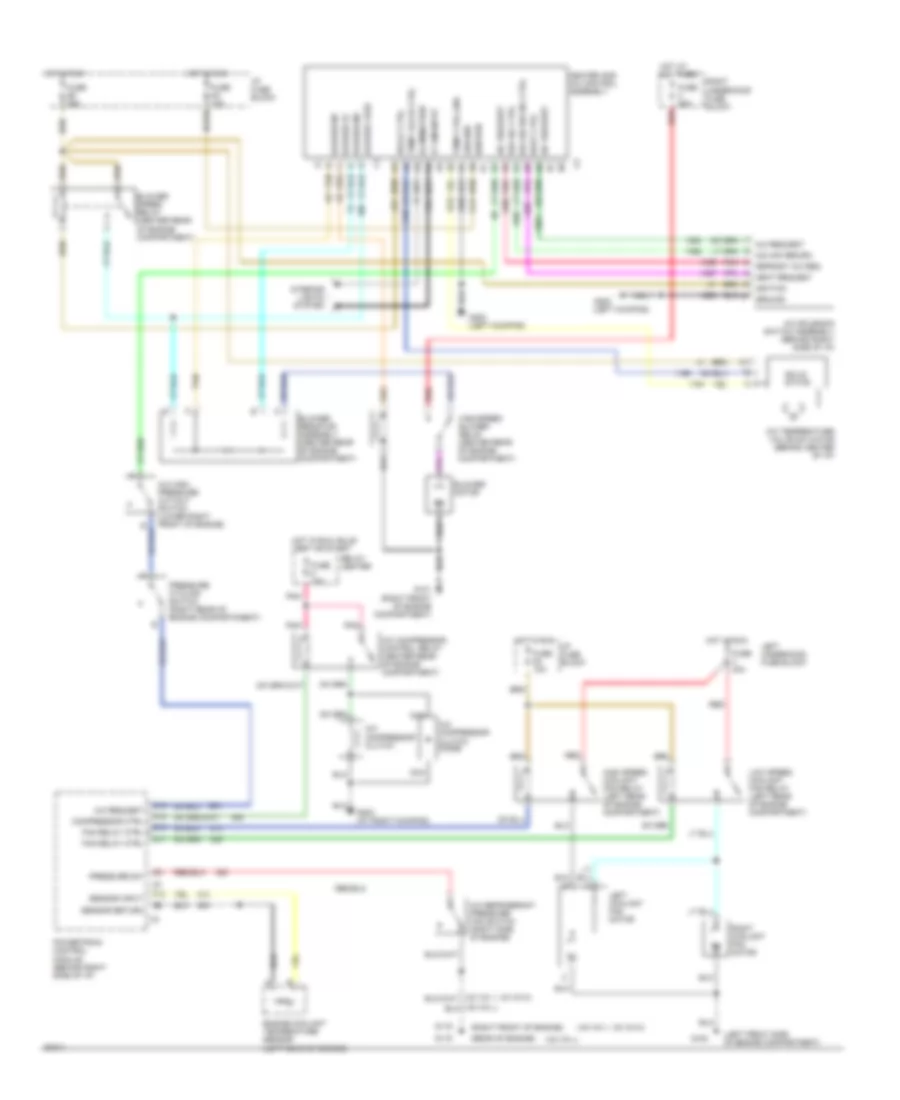
A/C Wiring Diagram, Auto A/C (2 of 2) for Buick Park Avenue Ultra 1995
List of elements for A/C Wiring Diagram, Auto A/C (2 of 2) for Buick Park Avenue Ultra 1995:
- (left front side of engine compartment)
- (right front of engine)
- A/c high pressure cut-out switch (lower right front of engine)
- A/c refrigerant pressure fan switch (right side of engine)
- A/c request
- C16
- Compressor control
- D10
- D11
- D12
- Engine coolant temperature sensor (left rear of engine)
- F13
- Fan relay control
- Fuse 40a
- Fuse 5c 10a
- G100
- G119
- G200 (left kick pad)
- G203 (right kickpad)
- Ground
- Heater and a/c control assembly
- High speed coolant fan relay (left rear of engine compartment)
- Hot in run
- I/p fuse block
- Ignition
- Illumination
- Interior lights system
- Left coolant fan motor
- Left underhood fuse block
- Low speed coolant fan relay (left rear of engine compartment)
- Nca
- Passenger climate control assembly
- Powertrain control module (behind right side of i/p)
- Pressure cycling switch (right rear of engine compartmnent)
- Pressure switch input
- Red
- Right coolant fan motor
- Sensor input
- Sensor return
- Tan
- Vf dim input
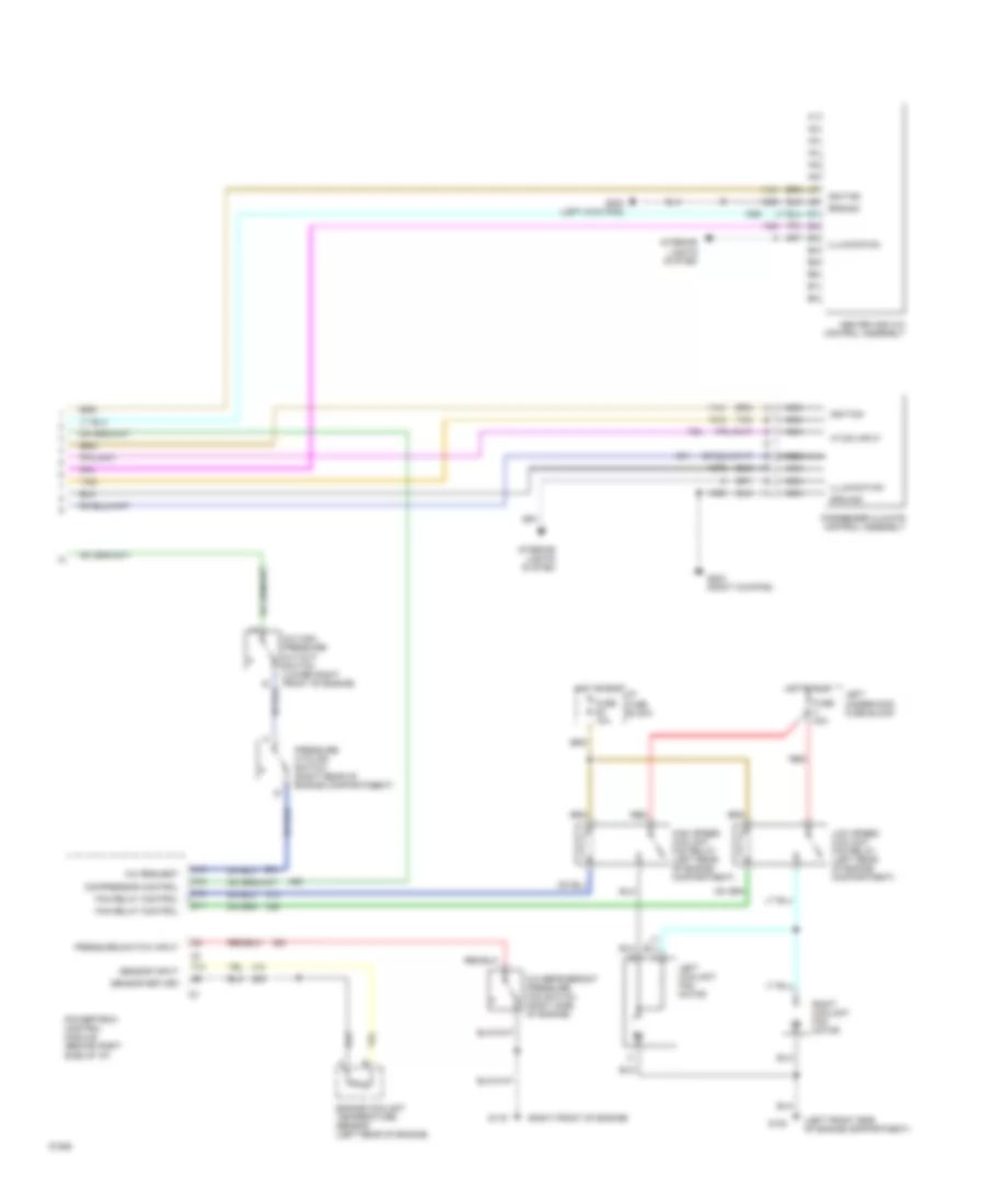
A/C Wiring Diagram, Manual A/C for Buick Park Avenue Ultra 1995
List of elements for A/C Wiring Diagram, Manual A/C for Buick Park Avenue Ultra 1995:
- (left front side of engine compartment)
- (left kickpad)
- (rear of engine)
- (right front of engine)
- (v6 vin 1, v6 vin k)
- (v6 vin l)
- A/c compressor clutch
- A/c compressor clutch diode
- A/c compressor control relay (center rear of engine compartment)
- A/c high pressure cut-out switch (lower right front of engine)
- A/c refrigerant pressure fan switch (right side of engine)
- A/c request
- A/c solenoid switch assembly (behind right side of i/p)
- A/c temperature valve actuator (behind center of i/p)
- A4 nca
- B tan
- B3 pnk
- Blower feed
- Blower hi
- Blower m1
- Blower m2
- Blower motor
- Blower resistor assembly (center rear of engine compartment)
- Blower speed relay (center rear of engine compartment)
- C16
- Compressor ctrl
- D10
- D11
- D12
- Def-a/c ctrl
- Defrost a/c req
- Engine coolant temperature sensor (left rear of engine)
- F13
- Fan relay ctrl
- Fuse 15a
- Fuse 30a
- Fuse 40a
- Fuse 5a 10a
- Fuse 5c 10a
- Fuse 5d 25a
- G100
- G101 (right front of engine compartment)
- G115
- G119
- G200
- G200 (left kickpad)
- G203 (at right kickpad)
- Ground
- Heat ctrl
- Heat request
- Heater and a/c control assembly
- High speed blower relay (center rear of engine compartment)
- High speed coolant fan relay (left rear of engine compartment)
- Hot at all times
- Hot in run
- Hot in run, bulb test or start
- I/p fuse block
- Ignition
- Illumination
- Interior lights system
- Left coolant fan motor
- Left underhood fuse block
- Low speed coolant fan relay (left rear of engine compartment)
- Nca
- O/s air /recirc
- O/s air recirc ctrl
- Pnk
- Powertrain control module (behind right side of i/p)
- Pressure cycling switch (right rear of engine compartmnent)
- Pressure sw
- Red
- Relay center
- Relay ctrl
- Right coolant fan motor
- Right underhood fuse block
- Sensor input
- Sensor return
- Solid state
- Tan
- Temp ctrl gnd
- Temp valve ctrl
- Vf dim input