AIR CONDITIONING
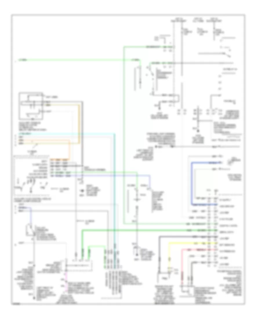
Automatic A/C Wiring Diagram, Short Wheel Base (1 of 2) for Buick Rainier 2005

List of elements for Automatic A/C Wiring Diagram, Short Wheel Base (1 of 2) for Buick Rainier 2005:
- (i/p harness, 15.5 cm from reci- rculation actuator connector)
- (i/p harness, 16 cm from sp201 breakout, toward dlc) s211
- (i/p harness, 5 cm from mode motor breakout, toward instrument cluster breakout)
- 5v ref
- A/c comp status
- A/c low press sw
- A10
- A11
- A12
- Air temp door ctrl
- Air temp dr pos sig
- Air temperature actuator (left) (behind left center of dash)
- Air temperature actuator (right) (behind right center of dash)
- Ambient air temp sig
- Ambient air temperature sensor (on left center of radiator support)
- Ambient light
- Ambient light/ sun load sensor assembly (on top center of dash, near base of windshield)
- B10
- B11
- B12
- Batt pos volt
- Battery
- Blower fuse 35 40a
- Blower motor (below right side of dash)
- Blower motor control module (lower right side of dash)
- Blwr mtr spd ctrl
- Class 2
- Def door pos sig
- Defrost actuator (behind upper left center of dash)
- Defrost door ctrl
- G102 (left side of underhood compt, near rear of underhood fuse block)
- G201
- G302 (on lower left "b" pillar)
- Ground
- Hot at all times
- Hot in run
- Hvac control module (center of dash)
- Hvac i fuse 39 10a
- Hvac-b fuse 36 10a
- Ign 3
- Inside air temp ctrl
- Inside air temp sig
- Inside air temperature sensor assembly (at top of left "b" pillar, behind trim)
- Interior lights system
- Left sensor
- Logic
- Low ref
- Low reference
- Lower left air temperature sensor (behind lower left center of dash, on air duct)
- Lower right air temperature sensor (behind lower right of dash, on air duct)
- Lps dimming ctrl
- Lwr lt air temp sig
- Lwr rt air temp sig
- Mode actuator (behind upper left center of dash)
- Mode door ctrl
- Mode door pos sig
- Nca
- Rear fuse block (below left rear seat)
- Recirc door cntrl
- Recirc dr pos sig
- Recirculation actuator (behind upper right side of dash)
- Red
- Right sensor
- S216
- S217
- S271 (i/p harness, 14.5 cm from dash compt, lamp breakout, toward center of dash)
- Solid state
- Sp201 (at lower right front of lower console)
- Tan
- Toward dlc breakout)
- Under- hood fuse block (on left side of engine compt)
- Upper left air temperature sensor (behind upper left center of dash)
- Upper right air temperature sensor (behind upper right center of dash)
- Uppr lt air temp sig
- Uppr rt air temp sig
- W/ rear a/c
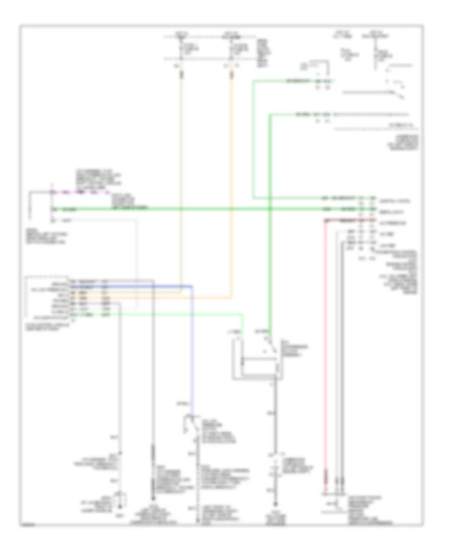
Automatic A/C Wiring Diagram, Short Wheel Base (2 of 2) for Buick Rainier 2005
List of elements for Automatic A/C Wiring Diagram, Short Wheel Base (2 of 2) for Buick Rainier 2005:
- (5.3l)
- (forward lamp harness, 20 cm from windshield washer pump breakout, toward engine cooling fan breakout) s113
- (left front of underhood compt, on left side of radiator support) g103
- (not used)
- +5v ref
- 0-12v pulse
- 4.2l
- 4.2l 5.3l
- 5.3l
- A/c compressor clutch assembly
- A/c fuse 30 10a
- A/c low pressure switch (at right rear of engine compt, on accumulator)
- A/c press sig
- A/c relay 44
- A12
- Air conditioning refrigerant pressure sensor (on high pressure line near a/c compressor)
- Ambient light sens
- Aux blwr hi spd
- Aux blwr med spd
- Aux mode dr
- Auxiliary blower motor (w/ rear a/c) (below center of dash)
- Auxiliary console mode actuator (w/ rear a/c) (below center of dash)
- Auxiliary hvac control module (under lower console)
- B11
- B12
- Batt
- Body control module (bcm) (beneath left rear seat, on rear fuse block)
- Class 2 data
- Comp rly cntrl
- Cooling fan (4.2l: front of engine)
- D11
- Data link connector (on bottom of left side of dash)
- E12
- Ect sens sig
- Engine coolant temperature (ect) sensor (4.2l: upper left side of engine) (5.3l: on left front of engine block, near generator)
- F12
- Fan fuse 20 10a
- Fan relay
- G103 (left front of underhood compt, on left side of radiator support)
- G107 (on lower left side of engine)
- G108 (on lower left side of engine)
- G201
- Ground
- Hall sensor
- High spd maf
- Hot at all times
- Hot in run or start
- Ign e fuse 22 10a
- Low ref
- Low reference
- Lt sunload sens sig
- Mode
- Off
- Powertrain control module (pcm) (4.2l) engine control module (ecm) (5.3l) (4.2l: on upper left side of engine) (5.3l: near lower left front of engine)
- Rt sunload sens sig
- S101 (in engine harness, 4cm from breakout to c107, towards ecm)
- S103 (forward lamp harness, 8 cm from rear washer pump breakout, toward toward right turn signal breakout)
- S232 (w/ immobilizer) (i/p harness, 10 cm from steering column breakout, toward shift control module)
- S307 (console harness)
- Serial data
- Sp201 (at lower right front of lower console)
- Sp205 (behind left of dash, near headlamp switch connector)
- Underhood fuse block (on left side of engine compt)
- W/ rear a/c
Compressor Wiring Diagram for Buick Rainier 2005
List of elements for Compressor Wiring Diagram for Buick Rainier 2005:
- (i/p harness, 10 cm from steering column breakout, toward shift control module) (w/ immobilizer) s232
- (left front of underhood compt, on left side of radiator support) g103
- +5v ref
- 4.2l 5.3l
- 5.3l 4.2l
- A/c compressor clutch assembly
- A/c comp status
- A/c fuse 30 10a
- A/c low press sw
- A/c low pressure switch (at right rear of engine compt, on accumulator)
- A/c press sig
- A/c relay 44
- A12
- Air conditioning refrigerant pressure sensor (on high pressure line near a/c compressor)
- B11
- B12
- Class 2
- Comp rly cntrl
- D11
- Data link connector (on bottom left side of dash)
- E12
- F12
- G102 (left side of underhood compt, near rear of underhood fuse block)
- G107 (on lower left side of engine)
- G201
- Ground
- Hot at all times
- Hot in run
- Hot in run or start
- Hvac 1 fuse 39 10a
- Hvac control module (center of dash)
- Hvac-b fuse 36 10a
- Ign 3
- Ign e fuse 22 10a
- Low ref
- Power
- Powertrain control module (pcm) (4.2l) engine control module (ecm) (5.3l) (4.2l: on upper left side of engine) (5.3l: near lower left front of engine)
- Rear fuse block (below left rear seat)
- S103 (forword lamp harness, 8 cm from rear washer pump breakout, toward right turn signal breakout)
- S202 (i/p harness, 16.5 cm from steering column connector breakout, toward dlc breakout)
- S211 (i/p harness, 16 cm from sp201 breakout, toward dlc)
- Serial data
- Sp201 (at lower right front of lower console)
- Sp205 (behind left of dash, near headlamp switch connector)
- Underhood fuse block (on left side of engine compt)