AIR CONDITIONING
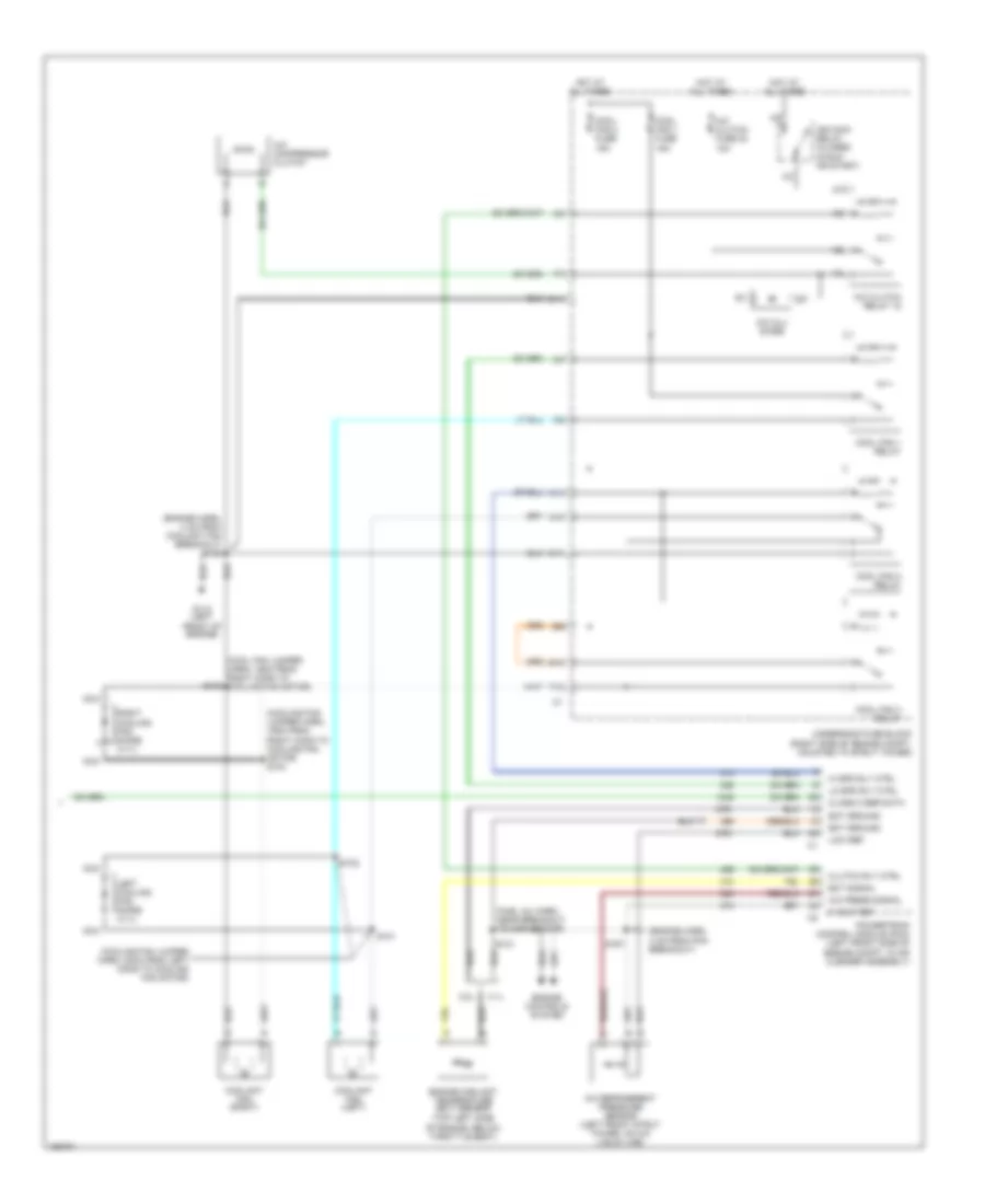
Automatic A/C Wiring Diagram (1 of 2) for Buick Regal GS 2002

List of elements for Automatic A/C Wiring Diagram (1 of 2) for Buick Regal GS 2002:
- (dash harn, 18 cm from radio breakout) s230
- (dash harn, 4 cm from breakout to radio)
- (dash harn, 4 cm from radio breakout)
- (on right side of of hvac module) vacuum/ electric solenoid
- (right side of dash) g200
- (right side of dash) g201
- 5 v ref
- A/c solenoid
- Air temp dr ctrl
- Air temperature actuator (left) (left side of hvac module)
- Air temperature actuator (right) (right side of hvac module)
- Air temperature sensor (inside) (below instrument cluster)
- Ambient air temperature sensor (front of radiator support)
- Ambient temp sig
- Battery
- Bi-level solenoid
- Blower motor (in hvac module)
- Blower motor control processor (right side of dash, in hvac module)
- Blower speed ctrl
- C10
- C11
- C12
- C13
- C14
- C15
- C16
- Class 2 serial data
- Cntrl in
- D10
- D11
- D12
- D13
- D14
- D15
- D16
- Data link connector (dlc) (under left side of dash, right of steering column)
- Def mode sol ctrl
- Defrost solenoid
- Gnd
- Grd
- Heater solenoid
- High blower fuse 30a
- Hot at all times
- Hot in run
- Hvac control module
- Hvac fuse 10a
- I/p fuse block (behind right side of dash)
- Ign 3 voltage
- Inside temp sig
- Interior lights system
- Ip dim sw sig
- Low ref
- Lt temp dr pos
- Lwr mode sol ctrl
- Mix-blnd sol ctrl
- Nca
- Radio,hvac, rfa, cluster data link fuse 15a
- Rear defogger system
- Recirc sol ctrl
- Recirc solenoid
- Red
- Rr defog rly ctrl
- Rt temp dr ctrl
- Rt temp dr pos
- S202 (dash harn, right of steering column)
- S231 (dash harn, 34 cm from heater-a/c control breakout)
- S233
- S258
- Solid state
- Sp205 (right side of steering column)
- Spd cntrl
- Sun load sig
- Sunload sensor (top right side of dash, near) defogger outlet)
- Tan
- Upper mode sol ctrl
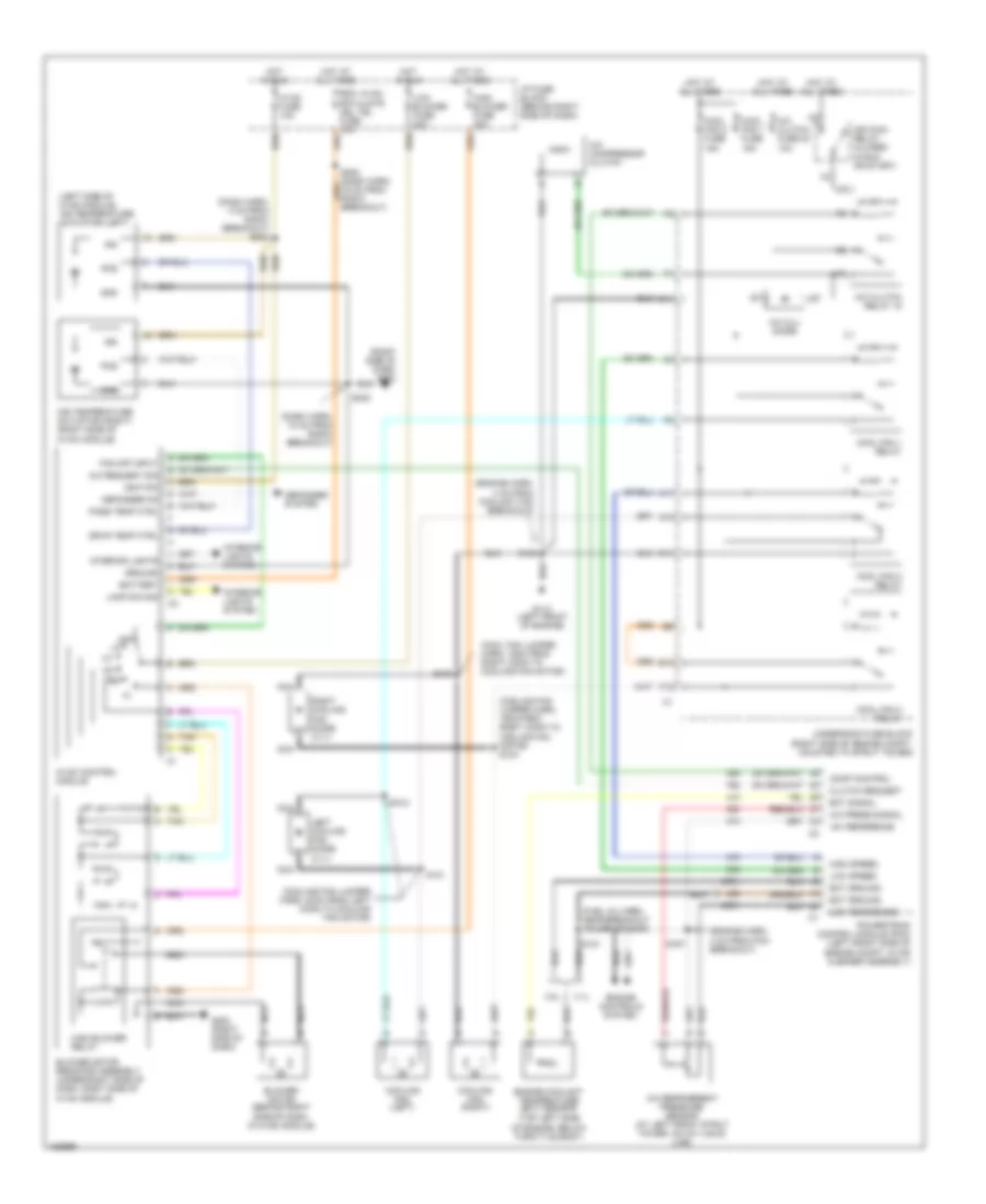
Automatic A/C Wiring Diagram (2 of 2) for Buick Regal GS 2002
List of elements for Automatic A/C Wiring Diagram (2 of 2) for Buick Regal GS 2002:
- (cool fan jumper harn, 19cm from right conn to cooling fan motor)
- (cooling fan jumper harn, 19cm from right conn to cooling fan motor) s104
- (cooling fan jumper harn, 20cm from left conn to cooling fan motor)
- (engine harn, 4 cm from coolant fan breakout) s105
- (engine harn, 4 cm from pcm breakout)
- (fuel inj harn, near breakout to map sensor)
- (top left side of engine, below throttle body)
- 3.1l
- 3.8l
- 5 volt ref
- A/c compressor clutch
- A/c clu diode
- A/c clutch fuse 23 10a
- A/c clutch relay 15
- A/c press signal
- A/c refrigerent pressure sensor (left front strut tower, on a/c liquid line)
- A10
- A11
- C11
- Class 2 ser data
- Clutch rly ctrl
- Cool fan 1 fuse 15a
- Cool fan 2 fuse 15a
- Cool fan 1 relay
- Cool fan 2 relay
- Cool fan 3 relay
- Coolant fan (left)
- Coolant fan (right)
- E10
- Ect ground
- Ect signal
- Engine controls system
- Engine coolant temperature (ect) sensor
- F12
- G113 (left front of engine)
- Hi spd rly ctrl
- Hot at all times
- Ign main relay (closed in run or start)
- Left cooling fan diode (3.1l)
- Lo spd rly ctrl
- Low ref
- Nca
- Powertrain control module (pcm) (left front side of engine compt, in air cleaner assembly)
- Right cooling fan diode (3.1l)
- S101
- S102
- S103
- S121
- S167
- Underhood fuse block (right side of engine compt, mounted to strut tower)
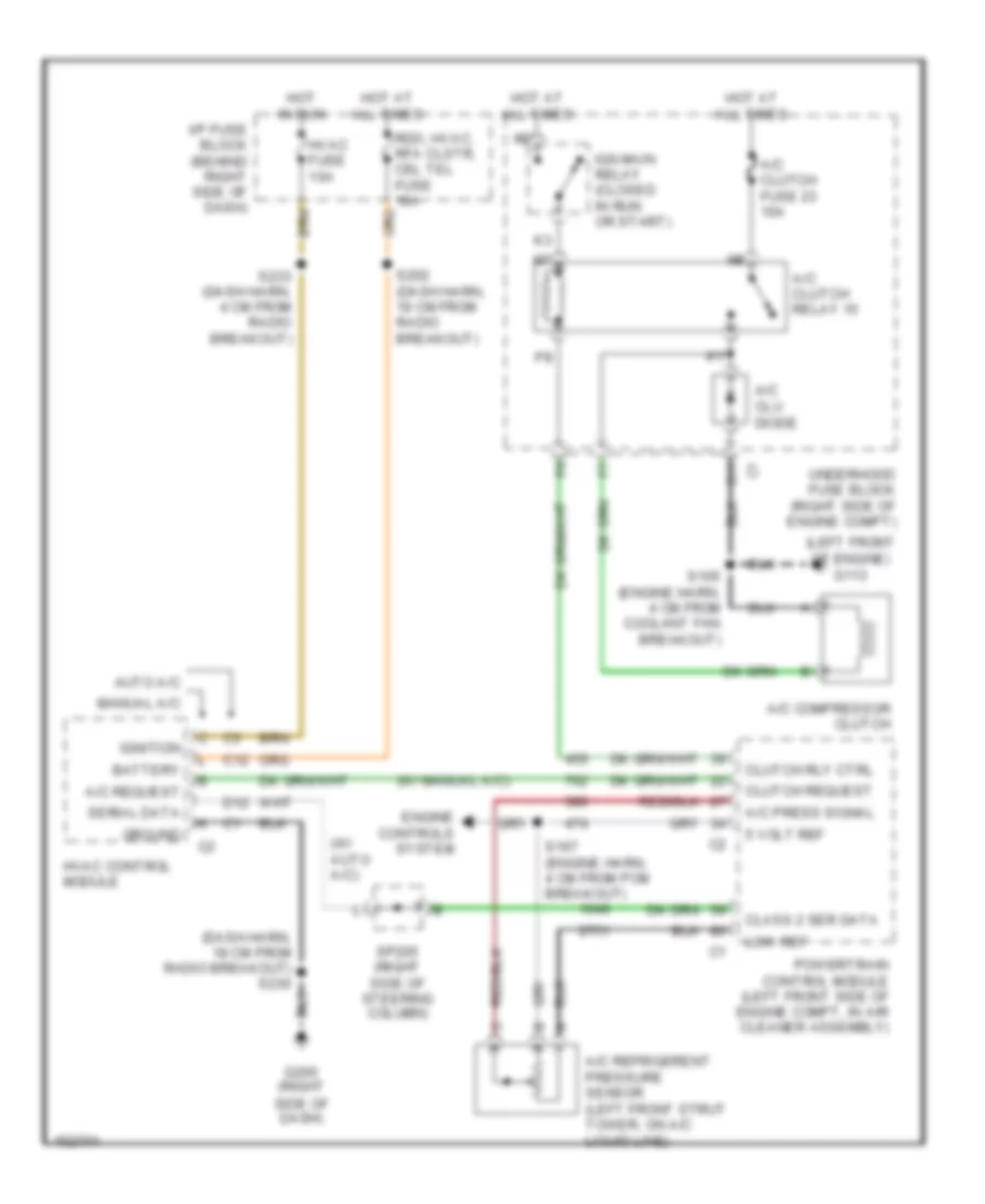
Compressor Wiring Diagram for Buick Regal GS 2002
List of elements for Compressor Wiring Diagram for Buick Regal GS 2002:
- (dash harn, 18 cm from radio breakout) s230
- (left front of engine) g113
- (w/ auto a/c)
- (w/ manual a/c)
- 5 volt ref
- A/c clu diode
- A/c clutch fuse 23 10a
- A/c clutch relay 15
- A/c compressor clutch
- A/c press signal
- A/c refrigerent pressure sensor (left front strut tower, on a/c liquid line)
- A/c request
- Auto a/c
- Battery
- C11
- C12
- Class 2 ser data
- Clutch request
- Clutch rly ctrl
- D12
- Engine controls system
- G200 (right side of dash)
- Ground
- Hot at all times
- Hot in run
- Hvac control module
- Hvac fuse 10a
- I/p fuse block (behind right side of dash)
- Ign main relay (closed in run or start)
- Ignition
- Low ref
- Manual a/c
- Powertrain control module (left front side of engine compt, in air cleaner assembly)
- Rdo, hvac, rfa clstr, cel tel fuse 10a
- S105 (engine harn, 4 cm from coolant fan breakout)
- S167 (engine harn, 4 cm from pcm breakout)
- S202 (dash harn, 19 cm from radio breakout)
- S233 (dash harn, 4 cm from radio breakout)
- Serial data
- Sp205 (right side of steering column)
- Underhood fuse block (right side of engine compt)
Manual A/C Wiring Diagram for Buick Regal GS 2002
List of elements for Manual A/C Wiring Diagram for Buick Regal GS 2002:
- (cool fan jumper harn, 19cm from right conn to cooling fan motor)
- (cooling fan jumper harn, 19cm from right conn to cooling fan motor) s104
- (cooling fan jumper harn, 20cm from left conn to cooling fan motor)
- (dash harn, 18 cm from radio breakout)
- (dash harn, 4 cm from radio breakout) s233
- (engine harn, 4 cm from coolant fan breakout)
- (engine harn, 4 cm from pcm breakout)
- (fuel inj harn, near breakout to map sensor)
- (left side of hvac module) air temperature actuator (left)
- (right side of dash) g200
- (top left side of engine, below throttle body)
- +5v reference
- 3.1l
- 3.8l
- A/c compressor clutch
- A/c clu diode
- A/c clutch fuse 23 10a
- A/c clutch relay 15
- A/c press signal
- A/c refrigerent pressure sensor (at left front strut tower, on a/c liquid line)
- A/c request sig
- A10
- A11
- Air temperature actuator (right) (right side of hvac module)
- Battery
- Blower motor (behind right side of dash, in hvac module)
- Blower motor resistor assembly (under right side of dash, right side of hvac module)
- C11
- Clutch request
- Comp control
- Cool fan 1 fuse 15a
- Cool fan 2 fuse 15a
- Cool fan 1 relay
- Cool fan 2 relay
- Cool fan 3 relay
- Cooling fan (left)
- Cooling fan (right)
- Defogger on
- Defogger system
- Drvr temp ctrl
- E10
- Ect ground
- Ect signal
- Engine controls system
- Engine coolant temperature (ect) sensor
- F12
- Fan off input
- G113 (left front of engine)
- G200 (right side of dash)
- Gnd
- Ground
- High blower fuse 30a
- High blower relay
- High speed
- Hot at all times
- Hot in run
- Hvac control module
- Hvac fuse 10a
- I/p fuse block (behind right side of dash)
- Ign
- Ign main relay (closed in run or start)
- Ignition
- Interior lights
- Interior lights system
- Lamp dim sig
- Left cooling fan diode (3.1l)
- Low blower fuse 20a
- Low reference
- Low speed
- Nca
- Nca nca
- Off
- Pass temp ctrl
- Pos
- Powertrain control module (pcm) (left front side of engine compt, in air cleaner assembly)
- Rdo, hvac, rfa clstr, cel tel fuse 10a
- Right cooling fan diode (3.1l)
- S101
- S102
- S103
- S105
- S121
- S167
- S230
- Tan
- Underhood fuse block (right side of engine compt, mounted to strut tower)