AIR CONDITIONING
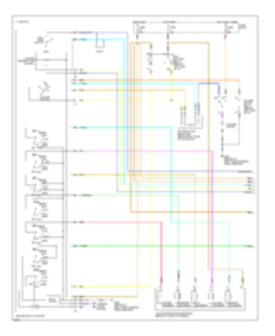
Air Conditioning Wiring Diagrams, Auto A/C (1 of 2) for Buick Regal Limited 1996

List of elements for Air Conditioning Wiring Diagrams, Auto A/C (1 of 2) for Buick Regal Limited 1996:
- (base of right "b" pillar)
- (behind i/p right side of brake pedal g202 bracket)
- (behind i/p, right of brake pedal bracket)
- +5 v
- A/c req to pcm
- A/c sol ctrl
- A/c solenoid
- Ambient outside temperature sensor (on center radiator support)
- Battery
- Bi-lev sol ctrl
- Bi-level solenoid
- Blower feedback
- Blower motor
- Blower motor control module (behind i/p, right of heater-a/c control module)
- Blw ctrl input
- Blw speed ctrl
- C 1995 vftc
- C10
- C11
- C12
- C13
- C14
- C15
- C16
- D10
- D11
- D12
- D13
- D14
- D15
- D16
- Data link
- Data link connector (bottom of i/p, right of steering column)
- Def sol ctrl
- Defrost solenoid
- E/m input
- Fuse 10a
- Fuse 15a
- Fuse 20a
- Fuse block
- G202
- G305
- Ground
- Heater and a/c control (center of i/p)
- Heater solenoid
- Hot at all times
- Hot in run
- Htr sol ctrl
- Ignition
- Illumination dim
- Inside air temperature sensor (right side of instrument cluster)
- Inside temp input
- Interior lights system
- Left electric actuator (left side of heater- a/c module)
- Lt elec actuator
- Motor drive
- Outside temp input
- Passenger heater- a/c select switch
- Passenger temp
- Radio
- Rear defog enable
- Rear defogger system
- Recirc sol ctrl
- Recirc solenoid
- Red
- Right electric actuator (right side of heater- a/c module)
- Rt elec actuator
- Sensor ground
- Serial data
- Solid state
- Tan
- Vacuum/ electric solenoid (behind i/p, right of plenum)
- Vf display dim input
- Volt to blw ctrl
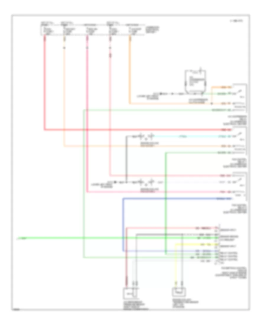
Air Conditioning Wiring Diagrams, Auto A/C (2 of 2) for Buick Regal Limited 1996
List of elements for Air Conditioning Wiring Diagrams, Auto A/C (2 of 2) for Buick Regal Limited 1996:
- +5v
- A/c comp fuse 10a
- A/c compressor clutch coil
- A/c compressor clutch diode
- A/c compressor relay (in underhood electrical center)
- A/c refrigerant pressure sensor (right side of engine compartment)
- A/c request
- B10
- C 1995 vftc
- C10
- Ecm bat fuse 20a
- Ecm ign fuse 15a
- Engine coolant temperature sensor (left top of engine)
- Engine cooling fan motor 1
- Engine cooling fan motor 2
- Fan control relay 1 (in underhood electrical center)
- Fan control relay 2 (in underhood electrical center)
- G110 (lower left front of engine)
- Hot at all times
- Hot in run
- Maxi fuse 1 60a
- Maxi fuse 3 60a
- Nca
- Pnk
- Powertrain control module (right side of engine compartment, forward of strut tower)
- Red
- Relay control
- Sensor ground
- Sensor input
- Underhood electrical center 1
Air Conditioning Wiring Diagrams, Manual A/C (1 of 2) for Buick Regal Limited 1996
List of elements for Air Conditioning Wiring Diagrams, Manual A/C (1 of 2) for Buick Regal Limited 1996:
- A/c solenoid
- B-lv
- Bi-level solenoid
- Blend
- Blower motor
- Blower motor relay (behind left side of i/p)
- Blower motor resistors (behind right side of a/c module)
- Blower switch
- C 1995 vftc
- Def
- Defrost solenoid
- Dual zone switch
- Fan control relay (behind left side of i/p)
- Fuse 15a
- Fuse 20a
- Fuse block
- G202 (behind i/p right side of brake pedal bracket)
- Heater and a/c control
- Heater solenoid
- Hot at all times
- Hot in run
- Htr
- Interior lights system
- Master temperature control
- Max
- Norm
- Off
- Recirc solenoid
- Red
- Solid state
- Tan
- Vacuum/electric solenoid box (behind i/p, right of plenum)
- Vnt
- Vnt b-lv
- W/cj3
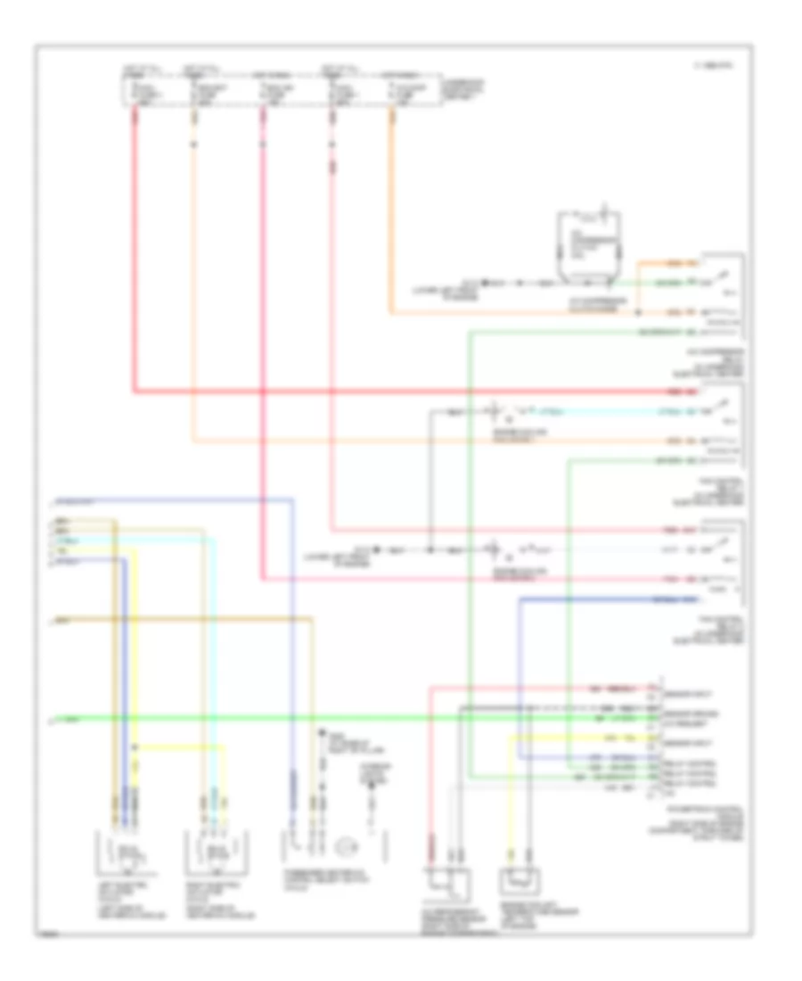
Air Conditioning Wiring Diagrams, Manual A/C (2 of 2) for Buick Regal Limited 1996
List of elements for Air Conditioning Wiring Diagrams, Manual A/C (2 of 2) for Buick Regal Limited 1996:
- (left side of heater-a/c module)
- (right side of heater-a/c module)
- (w/cj3)
- +5v
- A/c comp fuse 10a
- A/c compressor clutch coil
- A/c compressor clutch diode
- A/c compressor relay (in underhood electrical center)
- A/c refrigerant pressure sensor (right side of engine compartment)
- A/c request
- B10
- C 1995 vftc
- C10
- Ecm bat fuse 20a
- Ecm ign fuse 15a
- Engine coolant temperature sensor (left top of engine)
- Engine cooling fan motor 1
- Engine cooling fan motor 2
- Fan control relay 1 (in underhood electrical center)
- Fan control relay 2 (in underhood electrical center)
- G110 (lower left front of engine)
- G305 (at base of right "b" pillar)
- Hot at all times
- Hot in run
- Interior lights system
- Left electric actuator (w/cj3)
- Maxi fuse 1 60a
- Maxi fuse 3 60a
- Nca
- Passenger heater-a/c control select switch
- Pnk
- Powertrain control module (right side of engine compartment, forward of strut tower)
- Red
- Relay control
- Right electric actuator (w/cj3)
- Sensor ground
- Sensor input
- Solid state
- Underhood electrical center 1