AIR CONDITIONING
Automatic A/C Wiring Diagram for Buick Rendezvous CXL 2002

List of elements for Automatic A/C Wiring Diagram for Buick Rendezvous CXL 2002:
- (buick)
- (dash harn, 24 cm from stoplamp switch breakout)
- (dash harn, 4 cm from blwr motor resistor breakout)
- (dash harn, 4 cm from havac/radio harn breakout)
- (fuel inj harn, top center of engine)
- (fwd lamp harn, 5 cm from horn breakout)
- (pontiac)
- (pontiac) (buick)
- +5v reference
- 5 volt ref
- A/c compressor clutch
- A/c clu fuse 10a
- A/c clu relay 52
- A/c compressor clutch diode
- A/c press signal
- A/c refrigerent pressure sensor (left side
- A10
- A11
- A12
- B10
- B11
- B12
- Bat
- Blower motor (behind glove box)
- Blower motor control processor (in front of blower motor)
- Breakout)
- Center console fuse block (in floor console)
- Class 2 serial
- Comp control
- Computer data lines system
- Cool fan 1 fuse 30a
- Cool fan 1 relay 62
- Cool fan 2 fuse 30a
- Cool fan 2 relay 59 cool fan sp relay 59
- Cool fan 3 relay 61 cool fan 2 relay 61
- Cooling fan (left)
- Cooling fan (right)
- Defog rly ctrl
- Defogger system
- Ect sensor
- Engine controls sensor (map sensor)
- Engine coolant temperature (ect) sensor (top rear of engine, near thermostat housing)
- Evap temp sig
- Evaporator temperature sensor (on evaporator coil)
- F10
- G100 (right side of engine compt)
- G117 (left rear of engine)
- G200 (behind right side of dash)
- Gnd
- Hi spd fan ctrl
- Hot at all times
- Hot in run or start
- Hvac control module (center of dash, below radio)
- I/p lamp sply
- Ign 1 main relay (closed in run or start)
- Ign 3 fuse 40a
- Ign 3 voltage
- Ign hvac fuse 10a c1
- Interior lights system
- Ip mdl fuse 10a
- Left air temperature actuator
- Lft temp dr ctrl
- Lft temp dr sig
- Lo spd fan ctrl
- Low ref
- Low reference
- Mode actuator
- Mode dr ctrl
- Mode dr sig
- Mtr spd ctrl
- Mtr spd sig
- Of engine compt, on accumulator)
- Powertrain control module (pcm) (left side of engine compartment, in air cleaner assembly)
- Recirc dr ctrl
- Recirculation actuator
- Red
- Right air temperature actuator
- Rt temp dr ctrl
- Rt temp dr sig
- S105
- S110
- S123
- S204
- S205
- S213
- Serial data
- Splice pack sp250
- Sunload sensor (center of dash)
- Sunload sig
- Tan
- Underhood fuse block (front of right wheel- house, above battery)
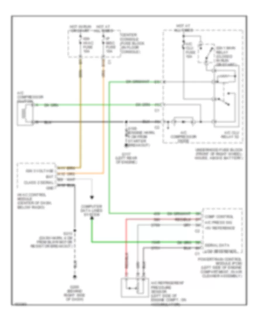
Compressor Wiring Diagram, with Auto A/C for Buick Rendezvous CXL 2002
List of elements for Compressor Wiring Diagram, with Auto A/C for Buick Rendezvous CXL 2002:
- +5v reference
- A/c compressor clutch
- A/c clu fuse 10a
- A/c clu relay 52
- A/c compressor diode
- A/c press sig
- A/c refrigerent pressure sensor (left side of engine compt, on accumulator)
- A10
- A11
- A12
- B10
- Bat
- Center console fuse block (in floor console)
- Class 2 serial
- Comp control
- Computer data lines system
- G117 (left rear of engine)
- G200 (behind right side of dash)
- Gnd
- Hot at all times
- Hot in run or start
- Hvac control module (center of dash, below radio)
- Ign 1 main relay (closed in run or start)
- Ign 3 voltage
- Ign hvac fuse 10a
- Ip misc fuse 10a
- Low reference
- Powertrain control module (pcm) (left side of engine compartment, in air cleaner assembly)
- S213 (dash harn, 4 cm from blwr motor resistor breakout)
- Serial data
- Underhood fuse block (front of right wheel- house, above battery)
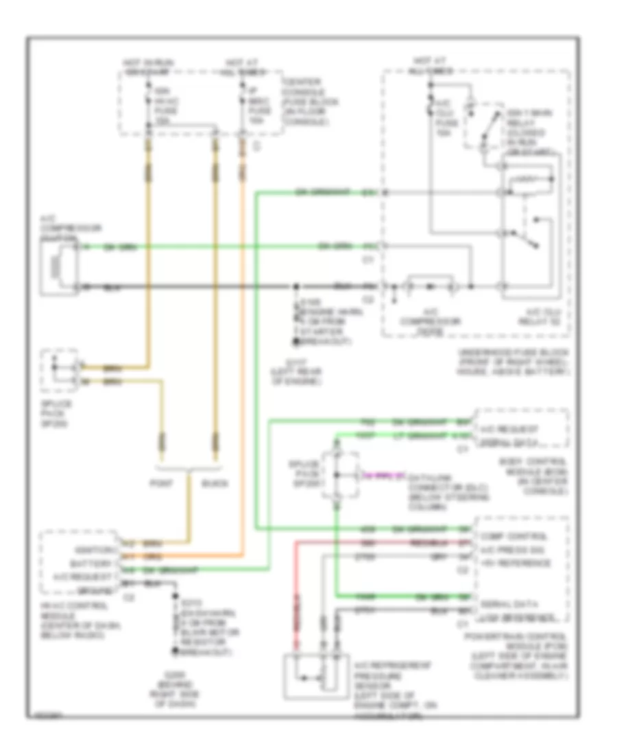
Compressor Wiring Diagram, with Manual A/C for Buick Rendezvous CXL 2002
List of elements for Compressor Wiring Diagram, with Manual A/C for Buick Rendezvous CXL 2002:
- +5v reference
- A/c compressor clutch
- A/c clu fuse 10a
- A/c clu relay 52
- A/c compressor diode
- A/c press sig
- A/c refrigerent pressure sensor (left side of engine compt, on accumulator)
- A/c request
- A10
- B10
- Battery
- Body control module (bcm) (in center console)
- Buick
- Center console fuse block (in floor console)
- Comp control
- Datalink connector (dlc) (below steering column)
- G117 (left rear of engine)
- G200 (behind right side of dash)
- Ground
- Hot at all times
- Hot in run or start
- Hvac control module (center of dash, below radio)
- Ign 1 main relay (closed in run or start)
- Ign hvac fuse 10a
- Ignition
- Ip misc fuse 10a
- Low reference
- Pont
- Powertrain control module (pcm) (left side of engine compartment, in air cleaner assembly)
- Resistor breakout)
- Serial data
- Splice pack sp205
- Splice pack sp250
- Underhood fuse block (front of right wheel- house, above battery)
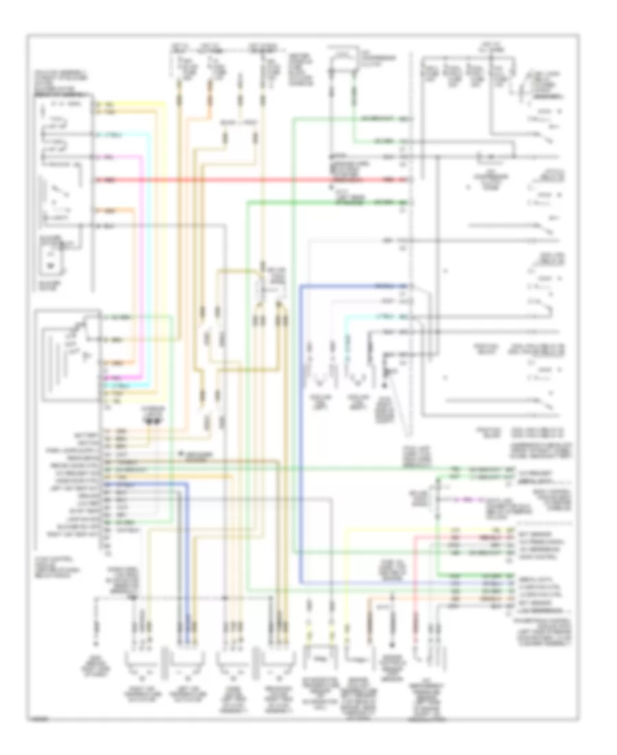
Manual A/C Wiring Diagram for Buick Rendezvous CXL 2002
List of elements for Manual A/C Wiring Diagram for Buick Rendezvous CXL 2002:
- (buick)
- (dash harn, 4 cm from blwr motor resistor breakout) s213
- (fuel inj harn, top center of engine)
- (fwd lamp harn, 5 cm from horn breakout)
- (on hvac assembly, in front of blower motor) blower motor resistor assembly
- (pontiac)
- (pontiac) (buick)
- +5v reference
- A/c compressor clutch
- A/c clu fuse 10a
- A/c clu relay 52
- A/c compressor clutch diode
- A/c press signal
- A/c refrigerent pressure sensor (left side
- A/c request
- A/c request sig
- A10
- B10
- Battery
- Blower motor
- Blower motor relay
- Blower sw off
- Body control module (bcm) (in center console)
- Breakout)
- Buick
- Center console fuse block (in floor console)
- Comp control
- Cool fan 1 fuse 30a
- Cool fan 1 relay 62
- Cool fan 2 fuse 30a
- Cool fan 2 relay 59 cool fan sp relay 59
- Cool fan 3 relay 61 cool fan 2 relay 61
- Cooling fan (left)
- Cooling fan (right)
- Data link connector (dlc) (below steering column)
- Defogger system
- Ect sensor
- Engine controls sensor (map sensor)
- Engine coolant temperature (ect) sensor (top rear of engine, near thermostat housing)
- Evap temp
- Evaporator temperature sensor (on evaporator coil)
- F10
- Frt blwr fuse 25a
- G100 (right side of engine compt)
- G117 (left rear of engine)
- G200 (behind right side of dash)
- Ground
- Hi spd fan ctrl
- Hot at all times
- Hot in run
- Hot in run or start
- Hvac control module (center of dash, below radio)
- Ign 1 main relay (closed in run or start)
- Ign 3 fuse 40a
- Ign hvac fuse 10a c1
- Ignition
- Interior lights system
- Ip misc fuse 10a
- Lamp dim sig
- Left air temp act
- Left air temperature actuator
- Lo spd fan ctrl
- Low ref
- Low reference
- Mode door ctrl
- Mode motor (left end of hvac assembly)
- Of engine compt, on accumulator)
- Off
- Pont
- Powertrain control module (pcm) (left side of engine compartment, in air cleaner assembly)
- Rear defog
- Recir/osa motor (right end of hvac assembly)
- Recirc door ctrl
- Red
- Right air temp act
- Right air temperature actuator
- S105
- S110
- S123
- Serial data
- Splice pack sp205
- Splice pack sp250
- Tan
- Underhood fuse block (front of right wheel- house, above battery)