AIR CONDITIONING
Automatic A/C Wiring Diagram for Buick Rendezvous Ultra 2005

List of elements for Automatic A/C Wiring Diagram for Buick Rendezvous Ultra 2005:
- (3.4l: fuel injector harness, 5 cm from c102)
- (3.6l)
- (center dash next to light sensor) sp250
- (engine harness, top right side of radiator, 6 cm from starter breakout)
- (i/p harness, center of dash, 4 cm from blower motor resistor breakout)
- (i/p harness, right side of dash, 24 cm from stoplamp switch breakout)
- (i/p harness, right side of dash, 4 cm from hvac/
- (or 2709)
- (or 2759)
- (or 470)
- +5v reference
- 3.4l
- 3.6l
- 5 volt ref
- A (3.4l)
- A/c compressor clutch (3.4l: right front lower engine) (3.6l: left front engine)
- A/c clu rly ctrl
- A/c clutch fuse 10a
- A/c clutch relay 51
- A/c compressor clutch diode 70
- A/c press signal
- A/c refrigerant pressure sensor (left side of engine compartment, below air cleaner assembly)
- A10
- A11
- A12
- B10
- B11
- B12
- Bat
- Blower motor (part of hvac module, behind glove box)
- Blower motor control processor (part of hvac module, behind glove box, in front of blower motor)
- Center console fuse block (in floor console)
- Class 2 serial
- Computer data lines system
- Cool fan 1 fuse 30a
- Cool fan 1 relay 61
- Cool fan 2 fuse 30a
- Cool fan 2 relay 58
- Cool fan 3 relay 60
- Defog rly ctrl
- Defogger system
- Early production
- Ect sensor
- Engine controls system
- Engine coolant temperature (ect) sensor (on top rear of engine, near thermostat housing)
- Evap temp sig
- Evaporative temperature sensor (in hvac module, mounted to evaporator coil)
- F10
- G100 (right side of engine compartment, on top of front end upper cross member)
- G117 (engine compartment, on bell housing, above starter)
- G132
- G200 (right side of dash, on underside of cross-car beam)
- Gnd
- Hi spd fan ctrl
- Hot at all times
- Hot in run
- Hvac control module (center of dash, below radio)
- I/p lamp sply
- Ign 3 fuse 40a
- Ign 3 hvac fuse 10a
- Ign 3 voltage
- Ignition relay 59 (3.4l) ptrain relay 59 (3.6l)
- Interior lights system
- Ip mdl fuse 10a
- Late production
- Left air temperature actuator (left side of hvac module)
- Left cooling fan (mounted to rear left side of radiator)
- Lft temp dr ctrl
- Lft temp dr sig
- Lo spd fan ctrl
- Logic
- Low ref
- Low reference
- Mode actuator (on left end of hvac assembly)
- Mode dr ctrl
- Mode dr sig
- Mtr spd ctrl
- Mtr spd sig
- Power distribution system
- Powertrain control module (pcm) (3.4l) engine control module (ecm) (3.6l) (3.4l: at left side of engine compt, in air cleaner assembly)
- Radio harness breakout)
- Recirc dr ctrl
- Recirculation actuator (in dash, behind glove box, on cowling)
- Red
- Right air temperature actuator (right side of hvac module)
- Right cooling fan (mounted to rear right side of radiator)
- Rt temp dr ctrl
- Rt temp dr sig
- S103
- S105
- S108 (3.4l)
- S110 (3.4l)
- S120 (3.6l)
- S125 (3.6l)
- S204
- S205
- S213
- S221
- Serial data
- Sunload sensor (center of dash, mounted to trim plate, near windshield defrost vent)
- Sunload sig
- Tan
- Underhood fuse block (front of right wheelhouse, above battery)
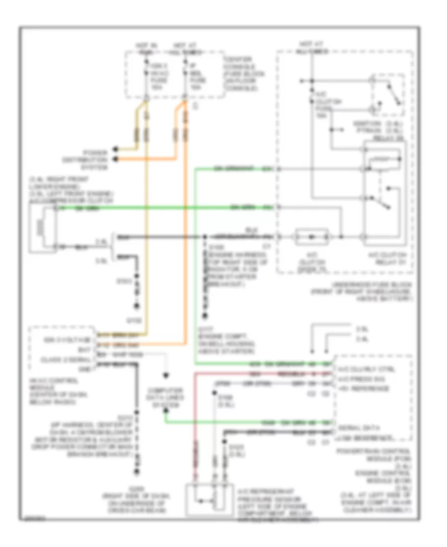
Compressor Wiring Diagram, with Auto A/C for Buick Rendezvous Ultra 2005
List of elements for Compressor Wiring Diagram, with Auto A/C for Buick Rendezvous Ultra 2005:
- (3.4l) (3.6l) relay 59
- (3.4l: right front lower engine) (3.6l: left front engine) a/c compressor clutch
- (or 2709)
- (or 2759)
- +5v reference
- 3.4l
- 3.6l
- A/c clu rly ctrl
- A/c clutch diode 70
- A/c clutch fuse 10a
- A/c clutch relay 51
- A/c press sig
- A/c refrigerant pressure sensor (left side of engine compartment, below air cleaner assembly)
- A10
- A11
- A12
- B10
- Bat
- Center console fuse block (in floor console)
- Class 2 serial
- Computer data lines system
- G117 (engine compt, on bell housing, above starter)
- G132
- G200 (right side of dash, on underside of cross-car beam)
- Gnd
- Hot at all times
- Hot in run
- Hvac control module (center of dash, below radio)
- Ign 3 hvac fuse 10a
- Ign 3 voltage
- Ignition ptrain
- Ip mdl fuse 10a
- Low reference
- Power distribution system
- Powertrain control module (pcm) (3.4l) engine control module (ecm) (3.6l) (3.4l: at left side of engine compt, in air cleaner assembly)
- S103
- S105 (engine harness, top right side of radiator, 6 cm from starter breakout)
- S108 (3.6l)
- S125 (3.6l)
- S213 (i/p harness, center of dash, 4 cm from blower motor resistor & auxiliary drop power connector main branch breakout)
- Serial data
- Underhood fuse block (front of right wheelhouse, above battery)
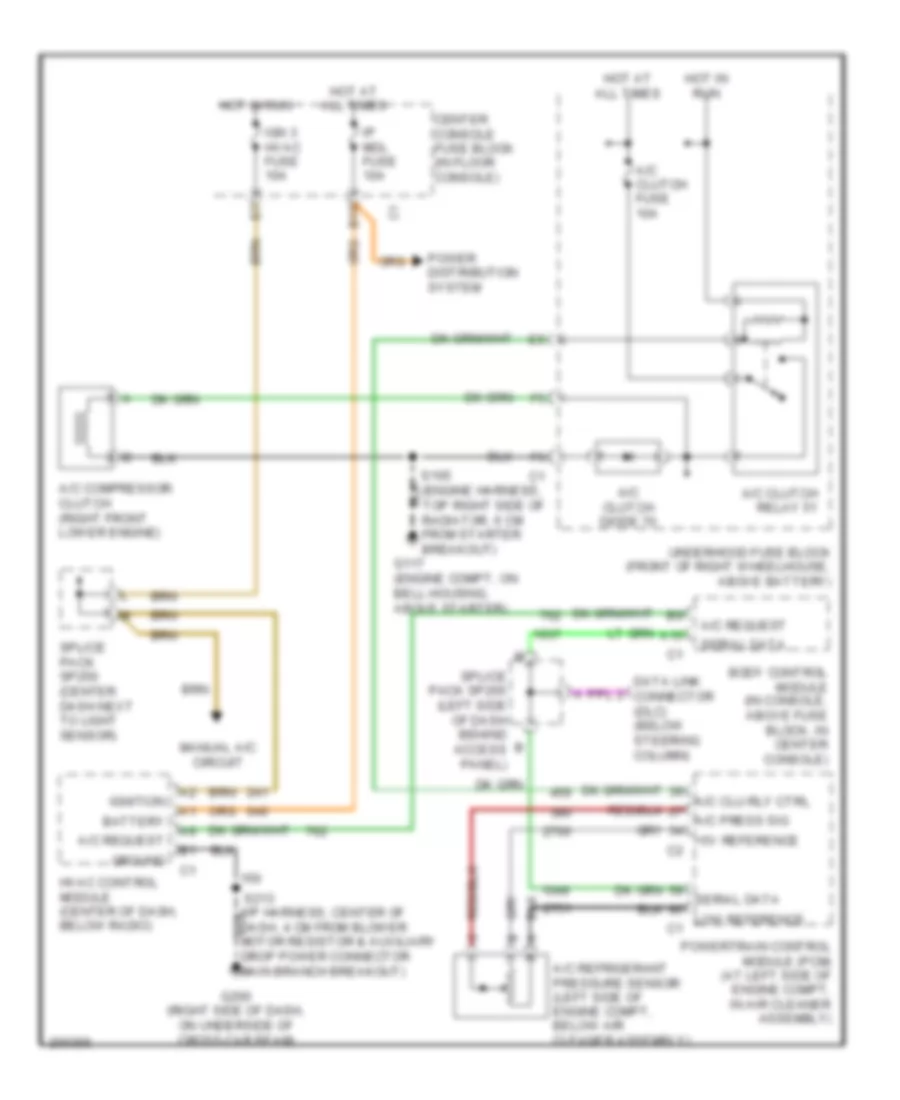
Compressor Wiring Diagram, with Manual A/C for Buick Rendezvous Ultra 2005
List of elements for Compressor Wiring Diagram, with Manual A/C for Buick Rendezvous Ultra 2005:
- A/c clu rly ctrl a/c press sig +5v reference c2
- A/c clutch diode 70
- A/c clutch fuse 10a
- A/c clutch relay 51
- A/c compressor clutch (right front lower engine)
- A/c refrigerant pressure sensor (left side of engine compt, below air cleaner assembly)
- A/c request
- A10
- B10
- Battery
- Body control module (in console, above fuse block, in center console)
- Center console fuse block (in floor console)
- Data link connector (dlc) (below steering column)
- Drop power connector main branch breakout)
- G117 (engine compt, on bell housing, above starter)
- G200 (right side of dash, on underside of cross-car beam)
- Ground
- Hot at all times
- Hot in run
- Hvac control module (center of dash, below radio)
- Ign 3 hvac fuse 10a
- Ignition
- Ip mdl fuse 10a
- Manual a/c circuit
- Power distribution system
- Powertrain control module (pcm) (at left side of engine compt, in air cleaner assembly)
- S105 (engine harness, top right side of radiator, 6 cm from starter breakout)
- Serial data
- Serial data low reference c1
- Splice pack sp205 (left side of dash behind access panel)
- Splice pack sp250 (center dash next to light sensor)
- Underhood fuse block (front of right wheelhouse, above battery)
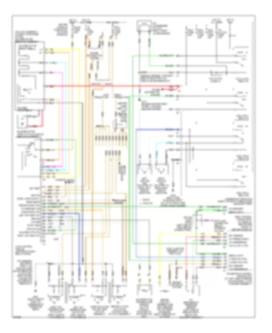
Manual A/C Wiring Diagram for Buick Rendezvous Ultra 2005
List of elements for Manual A/C Wiring Diagram for Buick Rendezvous Ultra 2005:
- (center dash next to light sensor) splice pack sp250
- (engine harness, top right side of radiator, 6 cm from starter breakout)
- (fuel injector harness, 5 cm from c102)
- (i/p harness, center of dash, 4 cm from blower motor resistor & auxiliary drop power connector main branch breakout)
- (left side of hvac module)
- (on hvac assembly, in front of blower motor) blower motor resistor assembly
- (right side of hvac module)
- +5v reference
- A/c compressor clutch (right front lower engine)
- A/c clu rly ctrl
- A/c clutch diode 70
- A/c clutch fuse 10a
- A/c clutch relay 51
- A/c press signal
- A/c refrigerant pressure sensor (left side of engine compt, below air cleaner assembly)
- A/c request
- A/c request sig
- A10
- B10
- Battery
- Blower motor (part of hvac module, behind glove box)
- Blower motor relay
- Blower motor resistors
- Blower mtr ctrl
- Blwr fuse 25a
- Body control module (bcm) (in console, above fuse block, in center console)
- Buick
- Center console fuse block (in floor console)
- Cool fan 1 fuse 30a
- Cool fan 1 relay 61
- Cool fan 2 fuse 30a
- Cool fan 2 relay 58
- Cool fan 3 relay 60
- Data link connector (below steering column)
- Defogger system
- Early production
- Ect sensor
- Engine controls system
- Engine coolant temperature (ect) sensor (on top rear of engine, near thermostat housing)
- Evap temp
- Evaporative temperature sensor (in hvac module, mounted to evaporator coil)
- F10
- G100 (right side of engine compt, on top of front end upper cross member)
- G117 (engine compartment, on bell housing, above starter)
- G200 (right side of dash, on underside of cross-car beam)
- Ground
- Hi spd fan ctrl
- Hot at all times
- Hot in run
- Hvac control module (center of dash, below radio)
- Ign 3 fuse 40a
- Ign 3 hvac fuse 10a c1
- Ignition
- Interior lights system
- Ip mdl fuse 10a
- Lamp dim sig
- Late production
- Left air temp act
- Left air temperature actuator
- Left cooling fan (mounted to rear left side of radiator)
- Lo spd fan ctrl
- Logic
- Low ref
- Low reference
- Mode actuator (on left end of hvac assembly)
- Mode door ctrl
- Off
- Pontiac
- Power distribution system
- Powertrain control module (pcm) (at left side of engine compartment, in air cleaner assembly)
- Rear defog
- Recirc door ctrl
- Recirculation actuator (on right end of hvac assembly)
- Red
- Right air temp act
- Right air temperature actuator
- Right cooling fan (mounted to rear right side of radiator)
- S105
- S110
- S213
- S221
- Serial data
- Splice pack sp205 (left side of dash behind access panel)
- Tan
- Underhood fuse block (front of right wheelhouse, above battery)