AIR CONDITIONING
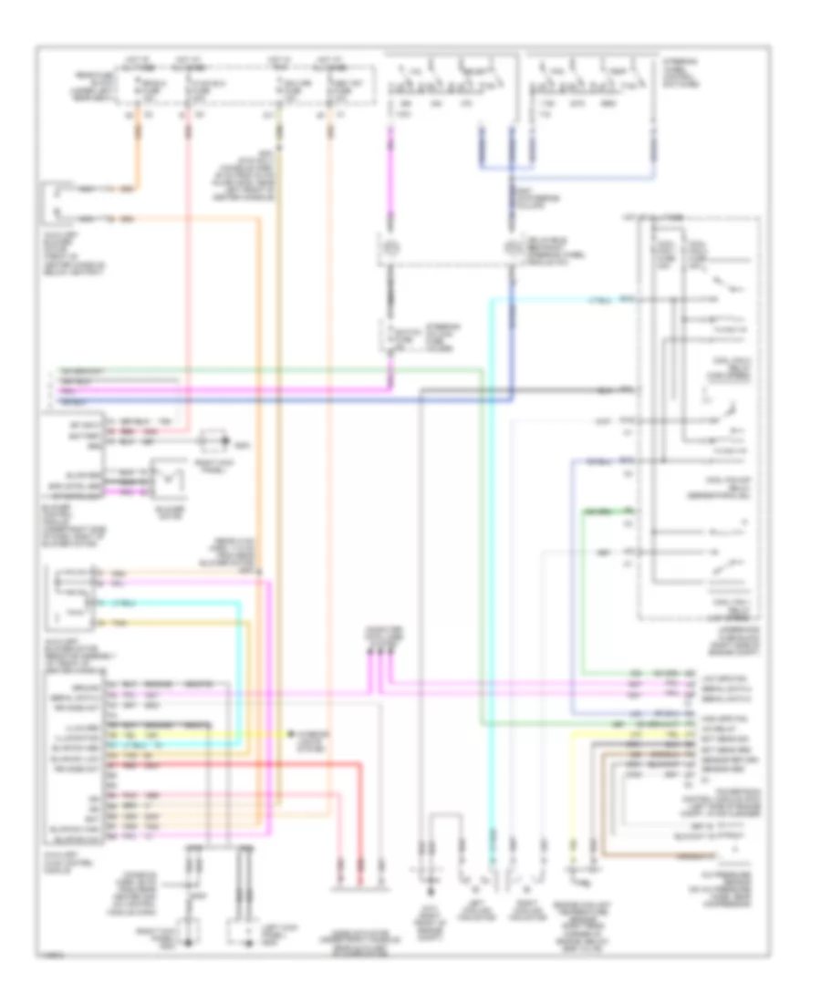
Automatic A/C Wiring Diagram (1 of 2) for Cadillac DeVille 2001

List of elements for Automatic A/C Wiring Diagram (1 of 2) for Cadillac DeVille 2001:
- inst panel
- (body harn, behind right side of dash)
- (dash harn, 65 cm from radio conn breakout)
- A/c clu fuse 15a
- A/c clutch
- A/c compressor clutch relay
- A/c low temp
- A/c low temperature sensor (rear of engine compt, on a/c low pressure line)
- A10
- A11
- A12
- Acc
- Air inlet act drv
- Air inlet act sig
- Air mix act drv
- Air mix act sig
- Air temperature actuator assembly (on right side of of hvac module)
- Ambient air temp sensor (on hood latch support)
- Aux
- Auxiliary air temp sensor (under front of console, near aux blower mtr)
- B10
- B11
- Bat
- Blwr spd cntrl
- C11
- Computer data lines system
- Dash integration module (dim) (behind right side of dash, near blower motor)
- Dim fuse 10a
- Drvr air mix drv
- Drvr air mix sig
- G110 (lower left front of engine)
- G203 (right kick panel)
- Ground
- Headlights system
- Hot at all times
- Hot in on
- Hot in on or start
- Hvac fuse 10a
- Iat sens cntrl
- Iat sens sig
- Ign
- Ign sw fuse 15a
- Ignition switch
- Inside air temperature sensor (behind left side of dash, left of steering column)
- Instrument panel integration module (above radio)
- Left air temperature actuator (on left side of hvac module)
- Left sun load sensor
- Lh sun load sens
- Lock
- Lower left air temp sensor (under left side of dash, in a/c dash)
- Lower right air temp sensor (under right side of dash, in a/c duct)
- Mode act drv
- Mode act sig
- Mode actuator (on left side of hvac module)
- Nca
- Pnk
- Rear fuse block (under left rear seat)
- Recirculation actuator (under right side of dash, right of blower motor)
- Red
- Rh sun load sens
- Right
- Right sun load sensor
- Rr air mix act drv
- Rr air mix act sig
- S205
- S207 (dash harn, 86 cm from
- S213 (body harn, behind left side of dash)
- S215
- Sensor return
- Serial data 2
- Start
- Steer whl ctrl
- Sunload sensor assembly (at top center of dash, in defogger grille)
- Tan
- Temp sens input
- Underhood fuse block (right side of engine compt)
- Upper left air temp sensor (under left side of dash, in a/c duct)
- Upper right air temp sensor (under right side of dash, in a/c duct)
- Voltage sens
Automatic A/C Wiring Diagram (2 of 2) for Cadillac DeVille 2001
List of elements for Automatic A/C Wiring Diagram (2 of 2) for Cadillac DeVille 2001:
- (console harn, 68 cm from rear heater and a/c control module conn)
- (left kick panel) g200
- (rear hvac harn, 17.5 cm from rear blower motor) s307
- (right kick panel)
- (right kick panel) g203
- 350(dhs)
- 450(dts)
- A/c pressure sensor (on a/c pressure hose, near compressor)
- A/c relay
- Auxiliary blower motor (front of center console, below ashtray)
- Auxiliary blower motor resistor assembly (at front of center console)
- Auxiliary hvac control module
- B10
- Bat
- Battery
- Blower control module (under right side of dash, right of blower motor)
- Blower motor
- Blwr grd
- Blwr sw high
- Blwr sw low
- Blwr sw m/h
- Blwr sw med
- Computer data lines system
- Cool fan 1 fuse 30a
- Cool fan 1 relay (low speed)
- Cool fan 2 fuse 30a
- Cool fan 2 relay (high speed)
- Cool fan s/p relay (series/parallel)
- Corner of engine, below egr valve)
- D10
- D11
- Dhs
- Dts
- E nca
- E10
- Ect sens grd
- Ect sens sig
- Engine coolant temperature sensor (right rear
- F11
- Fan
- G101 (right front of engine compt)
- G203
- Grd
- Ground
- High spd fan
- Hot at all times
- Hot in run
- Hvac blo fuse 40a
- Ign
- Ign 3 rr fuse 10a
- Illum grd
- Illumination
- Inflatable restraint steering wheel module coil
- Interior lights system
- Left cooling fan motor
- Low spd fan
- Mem t&t fuse 10a
- Mode actuator (under front console, near auxiliary blower motor)
- Nca
- Pnk
- Powertrain control module (pcm) (left side of engine compt, in air cleaner)
- Rear fuse block (under left rear seat)
- Red
- Right cooling fan motor
- Rr blo fuse 10a
- Rr mode act
- S227 (in steering column)
- S300
- S301 (dts only) (console harn, 50 cm from 30 pin inline conn, near left front of center console)
- Select
- Sensor grd
- Sensor return
- Serial data 2
- Sp cntrl out
- Sp input
- Spd cntrl grd
- Steering column fuse holder
- Steering wheel control switches
- Switch fuse 2a
- Tan
- Temp
- Underhood fuse block (right side of engine compt)
- Vol
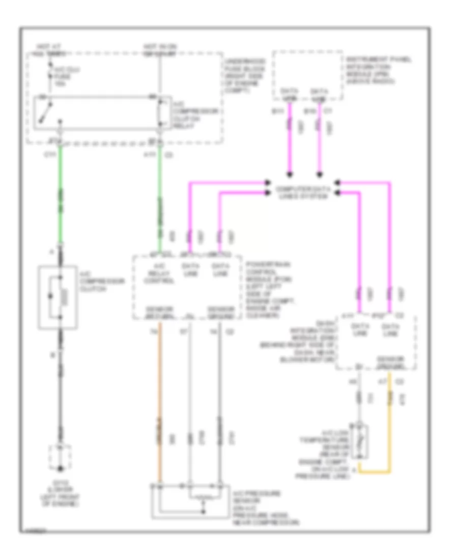
Compressor Wiring Diagram for Cadillac DeVille 2001
List of elements for Compressor Wiring Diagram for Cadillac DeVille 2001:
- A nca
- A/c clu fuse 15a
- A/c compressor clutch
- A/c compressor clutch relay
- A/c low temperature sensor (rear of engine compt, on a/c low a
- A/c pressure sensor (on a/c pressure hose, near compressor)
- A/c relay control
- A11
- A12
- B11
- C1 b10
- C11
- Computer data lines system
- Dash integration module (dim) (behind right side of dash, near blower motor)
- Data line
- G110 (lower left front of engine)
- Hot at all times
- Hot in on or start
- Instrument panel integration module (ipm) (above radio)
- Nca
- Powertrain control module (pcm) (left left side of engine compt, inside air cleaner)
- Pressure line)
- Sensor ground
- Sensor return
- Tan
- Underhood fuse block (right side of engine compt)