AIR CONDITIONING
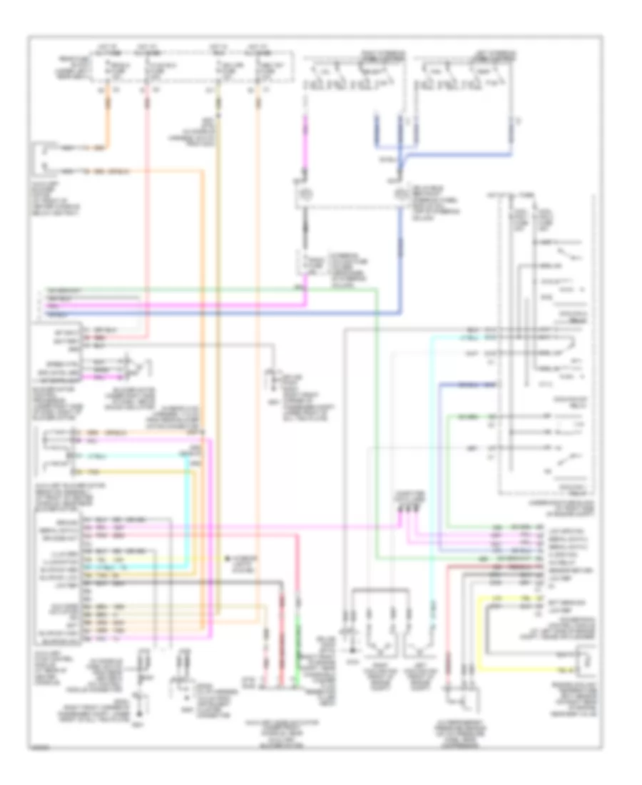
Automatic A/C Wiring Diagram (1 of 2) for Cadillac DeVille DHS 2005

List of elements for Automatic A/C Wiring Diagram (1 of 2) for Cadillac DeVille DHS 2005:
- (behind right side of dash, near blower motor) dash integration module
- (in body harness, 53.5 cm from c201)
- (in engine harness, 10 cm from map/ tps breakout)
- (in i/p harn, 65.5 cm from radio connector, between s202 & c201)
- (left front corner of engine, below thermostat housing, on transmission case) g100
- A/c clu fuse 15a
- A/c clu relay
- A/c compressor clutch (lower right side of engine)
- A/c compressor clutch solenoid
- A/c compressor temperature switch
- A/c low temp
- A/c refrigerant low temperature sensor (at rear of engine compt, on a/c low pressure line)
- A10
- A10 c1
- A11
- A12
- Acc
- Acc lock
- Air inlet act drv
- Air inlet act sig
- Air mix act drv
- Air mix act sig
- Air temperature actuator assembly (on right side of of hvac assembly)
- Ambient air temperature sensor (on hood latch support)
- Aux
- Auxiliary air temperature sensor (under front console, near auxiliary blower motor)
- B10
- B11
- B12
- Blwr spd cntrl
- C11
- Computer data lines system
- Dim fuse 10a
- Drvr air mix drv
- Drvr air mix sig
- Ground
- Headlights system
- Hot at all times
- Hot in on
- Hot in on or start
- Hvac fuse 10a
- Iat sens cntrl
- Iat sens sig
- Ign
- Ignition switch
- Inside air temperature sensor (behind left side of dash, left of steering column)
- Instrument panel integration module (above radio)
- Left air temperature actuator
- Left sun load sensor
- Lh sun load sens
- Lock
- Lower left air temperature sensor (under left side of dash, in a/c duct)
- Lower right air temperature sensor (under right side of dash, in a/c duct)
- Mode act drv
- Mode act sig
- Mode actuator (on left side of hvac assembly)
- Nca
- Off
- Pnk
- Power distribution system
- Rear fuse block (under left rear seat)
- Recirculation actuator (behind right side of dash, right of blower motor)
- Red
- Rh sun load sens
- Right
- Right sun load sensor
- Rr air mix act drv
- Rr air mix act sig
- S130
- S205
- S207 (in i/p harn, 86.1 cm from inst panel integration module conn c1)
- S213 (in body harness, 73.2 cm from c200)
- S215
- Sensor return
- Serial data 2
- Sp201 (right front corner of passenger compt, under front of sill trim plate) g201
- Start
- Steer whl ctrl
- Sun load sensor assembly (on top center of dash, in defogger grill)
- T10
- T11
- Tan
- Temp sens input
- Underhood fuse block (at right side of engine compt)
- Upper left air temperature sensor (under left side of dash, in a/c duct behind outer vent)
- Upper right air temperature sensor (under right side of dash, in a/c duct behind outer vent)
- V10
- V11
- Voltage sens
Automatic A/C Wiring Diagram (2 of 2) for Cadillac DeVille DHS 2005
List of elements for Automatic A/C Wiring Diagram (2 of 2) for Cadillac DeVille DHS 2005:
- (dhs)
- (dts)
- (in console harn, 68.5 cm from rear heater & a/c control module connector)
- (in rear hvac harness, 17.5 cm from rear blower motor connector) s307
- (or 450)
- A/c refrigerant pressure sensor (on a/c pressure hose, near compressor)
- A/c relay
- A10
- A11
- Aux mode actuator ign
- Auxiliary blower motor (at front of center console, below ashtray)
- Auxiliary blower motor resistor assembly (at front of center console, near rear blower motor)
- Auxiliary hvac control module (at rear of center console)
- Auxiliary mode actuator (under front console, near auxiliary blower motor)
- B10
- B11
- Bare
- Bat
- Battery
- Blower motor (under right side of dash, above sound insulator)
- Blower motor control processor (under right side of dash, right of blower motor)
- Blwr sw high
- Blwr sw low
- Blwr sw m/h
- Blwr sw med
- C10
- C11
- Computer data lines system
- Connector)
- Cool fan 1 fuse 30a
- Cool fan 2 fuse 30a
- Coolfan 1 relay
- Coolfan 2 relay
- Coolfan s/p relay
- D10
- D11
- Dhs
- Dts
- E nca
- E10
- E11
- Ect sens sig
- Engine coolant temperature (ect) sensor (on right rear of engine, near egr valve)
- F11
- Fan
- G nca
- G10
- G104
- G11
- G201
- Gnd
- Grd
- Ground
- Hi spd fan
- Hot at all times
- Hot in run
- Hvac blo fuse 40a
- Ign 3 rr fuse 10a
- Illum grd
- Illumination
- Inflatable restraint steering wheel module coil (top of steering column)
- Interior lights system
- Left cooling fan (front of engine compt)
- Left steering wheel control
- Low ref
- Low spd fan
- Mem t&t fuse 10a
- Nca
- Pnk
- Powertrain control module (at left side of engine compt, inside air cleaner)
- Radio fuse 2a
- Rear fuse block (under left rear seat)
- Red
- Right cooling fan (front of engine compt)
- Right steering wheel control
- Rr blo fuse 10a
- Rr mode act
- S300
- S301 (dts) (in console harness, 50.5 cm from c304)
- Select
- Sensor return
- Serial data 2
- Sp cntrl out
- Sp input
- Sp200 (in i/p harness, 18.5 cm from instrument cluster g200
- Sp201 (right front corner of passenger compt, under front of sill trim plate)
- Spd cntrl grd
- Speed ctrl
- Splice pack sp104 (right front of engine compt, near windshield washer fluid reservoir filler neck)
- Splice pack sp201 (right front corner of passenger compt, under front of sill trim plate)
- Steering column fuse holder (near base of steering column)
- Tan
- Temp
- Underhood fuse block (at right side of engine compt)
- Vol
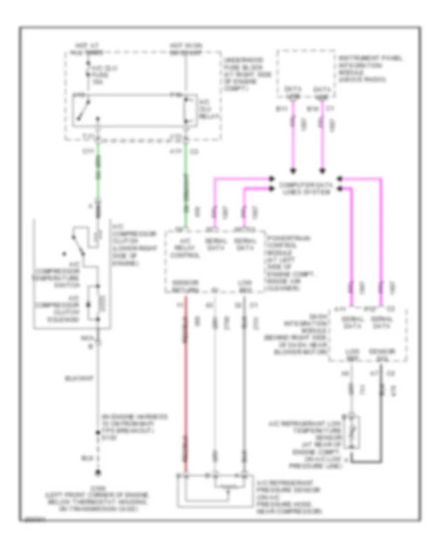
Compressor Wiring Diagram for Cadillac DeVille DHS 2005
List of elements for Compressor Wiring Diagram for Cadillac DeVille DHS 2005:
- (in engine harness, 10 cm from map/ tps breakout) s130
- A nca
- A/c clu fuse 15a
- A/c clu relay
- A/c compressor clutch (lower right side of engine)
- A/c compressor clutch solenoid
- A/c compressor temperature switch
- A/c refrigerant low temperature sensor (at rear of engine compt, on a/c low a
- A/c refrigerant pressure sensor (on a/c pressure hose, near compressor)
- A/c relay control
- A11
- A12
- B11
- C1 b10
- Computer data lines system
- Dash integration module (behind right side of dash, near blower motor)
- Data line
- G100 (left front corner of engine, below thermostat housing, on transmission case)
- Hot at all times
- Hot in on or start
- Instrument panel integration module (above radio)
- Low ref
- Nca
- Powertrain control module (at left side of engine compt, inside air cleaner)
- Pressure line)
- Sensor return
- Sensor sig
- Serial data
- T10
- T11
- Underhood fuse block (at right side of engine compt)
- V10
- V11