AIR CONDITIONING
A/C Wiring Diagram for Chevrolet Astro 1998

List of elements for A/C Wiring Diagram for Chevrolet Astro 1998:
- (eng harn, 5 cm from underhood fuse-relay center breakout)
- (right side of dash)
- A/c clutch diode (in underhood fuse-relay center)
- A/c comp mini fuse 10a
- A/c compressor clutch
- A/c enable
- A/c enable relay (in underhood fuse-relay center)
- A/c high pressure cut off switch (rear of a/c compressor)
- A/c low pressure cut off switch (top of a/c receiver dryer)
- A/c maxi fuse m3 30a
- A/c request
- B red
- Bi-lv
- Blend
- Blower motor resistor and relay pack (mounted on right front of dash housing, between evaporator and front blower motor)
- C218
- C219
- Convenience center
- Def
- Front blower motor
- G109 (right radiator support)
- G201
- G201 (right side of dash)
- G402 (below rear a/c blower)
- G409 (above rear heater)
- G901 (right front "a" pillar)
- Heat
- Heater and a/c control valve solenoid (behind receiver/ dryer)
- Hot at all times
- Hot in run
- Hot in run or start
- Htr-a/c fuse 12 20a
- Hvac control module
- I/p fuse block
- Ign-e mini fuse 10a
- Interior lights system
- Max
- Med
- Norm
- Off
- Pnk
- Rear a/c blower motor
- Rear a/c resistor pack (above rear blower motor, in duct)
- Rear a/c switch
- Rear heat-a/c relay (in underhood fuse-relay center)
- Rear heater blower motor
- Rear heater resistor pack (top rear heater core assembly)
- Rear heater switch
- Red
- Rr heat/a/c maxi fuse 30a
- S111
- S111 (eng harn, 17 cm from underhood fuse-relay center breakout)
- S111 (eng harn, 5 cm from underhood fuse-relay center breakout)
- S124 (engine harn, 13 cm from oil pressure switch breakout)
- S224 (i/p harness, 17 cm from headlamp switch connector breakout)
- S229 (i/p harn, 4 cm from temperature control motor connector breakout)
- S238 (i/p harn, behind left side of dash)
- Tan
- Temperature control motor (behind right side of dash, left side of air duct)
- Underhood fuse-relay center
- Vehicle control module (left side of engine compt)
- Vent
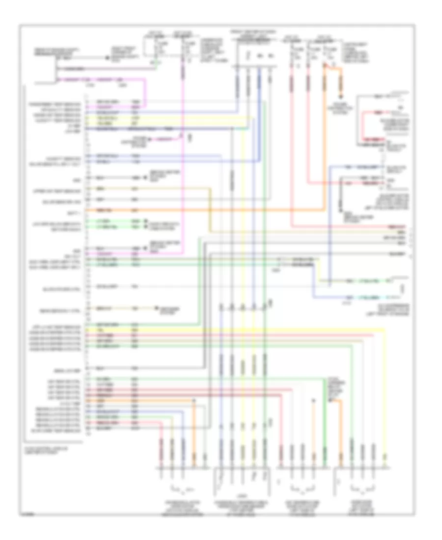
Compressor Wiring Diagram for Chevrolet Astro 1998
List of elements for Compressor Wiring Diagram for Chevrolet Astro 1998:
- (behind center of dash) g202
- (front center of dash) ambient light sunload sensor
- (hvac harness, below center of i/p) j271
- (rear of engine compt) air quality sensor
- (right front corner of engine compt) g104
- 5-volt ref
- 5v ref
- A/c compressor solenoid valve (left front of engine)
- Air quality sens sig
- Air recirculation door motor (on hvac module, above blower motor)
- Air temp dr ctrl
- Air temperature door actuator (left side of hvac module)
- B+ blwr mtr fan rly x2
- Batt +
- Blower motor (under right side of dash)
- Blower motor control module (on hvac module, left of blower motor)
- Blwr mtr spd ctrl
- Blwr mtr spd rly
- Computer data lines system
- Defogger system
- Ele varbl displment ctrl
- Ele varbl displment sply
- Evap core temp sens sig
- Fuse 10a
- Fuse 15a
- Fuse 30a
- Fuse 40a
- Fuse 5a
- G202 (behind center of dash)
- Gnd
- Gnd b+ x1
- Hot at all times
- Hot in on or start
- Humidity sens sig
- Humidity temp sens sig
- Hvac control module (center of dash)
- Ign volt
- Inside air temp sens sig
- Instrument panel fuse block (behind left end of dash)
- Logic
- Low ref
- Low spd gmlan ser data
- Mode door actuator (left side of hvac module)
- Mode dr stepper mtr ctrl
- Network bus 9
- Power distribution system
- Rear defog rly ctrl
- Recirculation dr ctrl
- Red
- Sens low ref
- Solar sens drv sig
- Solar sens pul sply volt
- Underhood fuse block (in engine compt, next to left strut tower)
- Upp lh air temp sens sig
- Upper air temp sens sig
- Windscreen temp sens sig
- Windshield temperature & inside moisture sensor (top center of windshield)
- X100
- X110
- X200
- X210
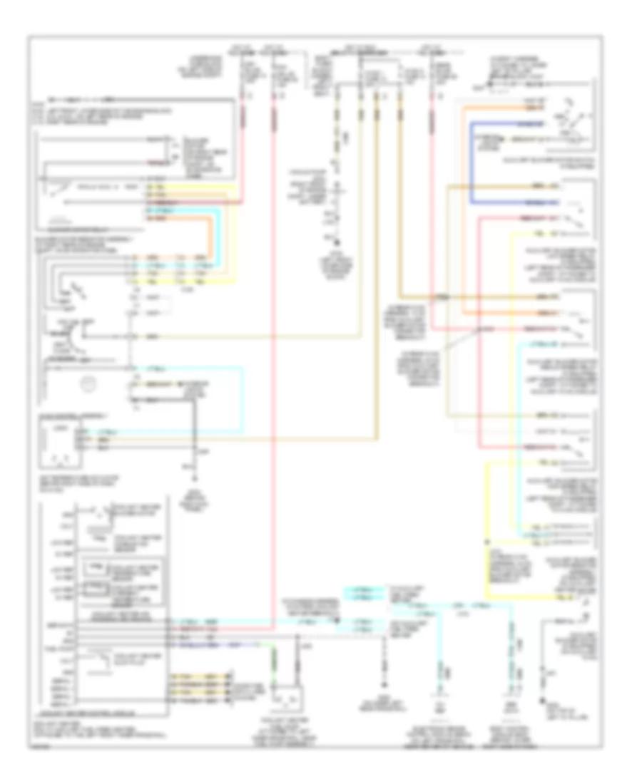
Heater Wiring Diagram for Chevrolet Astro 1998
List of elements for Heater Wiring Diagram for Chevrolet Astro 1998:
- (in body harness, attached to lower left "b" pillar) splice block jx347
- (in chassis harness, 15 cm from coolant heater breakout) j119
- (in rear hvac harness, 13 cm from auxiliary blower motor connector breakout)
- (in rear hvac harness, 20 cm from auxiliary blower motor connector breakout)
- 12v ref
- 5v ref
- A/c
- Air temperature actuator (behind right side of dash, on hvac)
- Auxiliary blower motor (if equipped) (on auxiliary hvac)
- Auxiliary blower motor high speed relay (if equipped) (left rear of passenger compt, attached to hvac module)
- Auxiliary blower motor low speed relay (if equipped) (left rear of passenger compt, attached to auxiliary hvac module)
- Auxiliary blower motor medium speed relay (if equipped) (left rear of passenger compt, attached to auxiliary hvac module)
- Auxiliary blower motor resistor assembly (if equipped) (on auxiliary heater motor)
- Auxiliary blower motor switch (if equipped)
- Bi-lev
- Blower motor (on right rear of engine compt, on evaporator case)
- Blower motor relay
- Blower motor resistor assembly (at right rear of engine compt, on evaporator case)
- Body control module (bcm) (behind lower right side of dash)
- Body fuse block (under left front seat) c8
- Computer data lines system
- Coolant heater (6.6l w/ auxiliary fuel fired heater) (attached to the left front inner frame rail)
- Coolant heater air temperature sensor
- Coolant heater blower motor
- Coolant heater combustion sensor
- Coolant heater control module
- Coolant heater fuel pump (attached to left inner frame rail, near fuel pump assembly)
- Coolant heater glow plug
- Coolant heater overheat temperature sensor
- Coolant heater temperature sensor
- Def
- Electronic brake control module (ebcm) (on left frame rail, near center of vehicle)
- Floor
- Foh mdl (d) fuse 35 15a
- Frt blwr fuse 74 40a
- Fuel pump
- G102 (6.6l: left front lower side of the engine block) (4.8l, 5.3l & 6.0l: on left rear of engine) (4.3l: right rear of engine)
- G102 (left front lower side of engine block)
- G304 (behind right kick panel)
- G347
- G400 (on inner left rear frame rail)
- G402 (on top of
- Gnd
- Hot at all times
- Hot w/ run relay k1 energized
- Hvac 1 fuse 14 20a
- Hvac 2 fuse 13 10a
- Hvac control assembly
- Interior
- Interior lights system
- J102
- J249
- J401
- J402
- J405
- J412
- J413 (in rear hvac harness, 24 cm from auxiliary blower motor breakout)
- Left "d" pillar)
- Lights system
- Logic
- Low ref
- Max a/c
- Med
- Mix-blend
- Off
- Rear blwr fuse 29 30a
- Red
- Ser data
- Serial +
- Serial -
- Tan
- Underhood fuse block (on left side of engine compt)
- Vacuum pump (6.6l) (right front of engine compt, under battery)
- Vent
- Volt
- W/ auxiliary fuel fired heater
- W/o auxiliary fuel fired heater
- X100
- X101