AIR CONDITIONING
Air Conditioning Wiring Diagrams for Chevrolet Beretta 1995
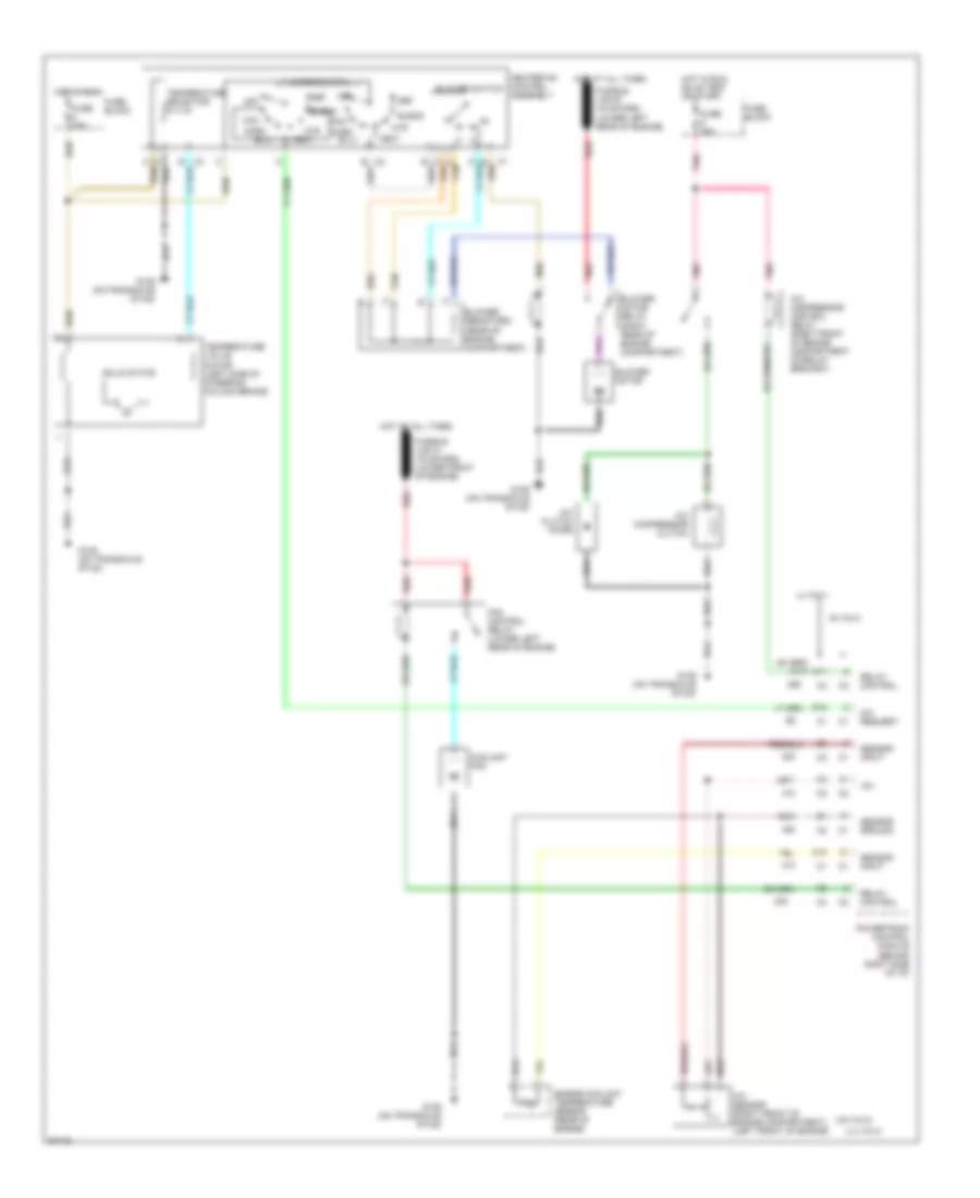
List of elements for Air Conditioning Wiring Diagrams for Chevrolet Beretta 1995:
- (l4 vin 4)
- (v6 vin m)
- +5v
- A/c clutch diode
- A/c compressor clutch
- A/c compressor control relay (right front of engine compartment on relay bracket)
- A/c request
- A/c sensor (right front of engine compartment) (left front of engine)
- Bi-lv
- Blend
- Blower motor
- Blower motor relay (right rear of engine compartment)
- Blower resistors (rear of engine compartment)
- Blower switch
- C tan
- C10
- C11
- Coolant fan
- D12
- Def
- Engine coolant temperature sensor (rear of engine)
- Fan control relay (lower left rear of engine)
- Fuse 20a
- Fuse 25a
- Fuse block
- G129 (on transaxle stud)
- Heater-a/c control assembly
- Hot at all times
- Hot in run
- Hot in run, bulb test or start
- Htr
- L4 vin 4
- Max
- Mode switch
- Norm
- Off
- Pnk
- Powertrain control module (behind right side of i/p)
- Red
- Relay control
- Sensor ground
- Sensor input
- Solid state
- Tan
- Temperature selector
- Temperature valve motor (left side of steering column brace)
- V6 vin m
- Vent
 English