AIR CONDITIONING
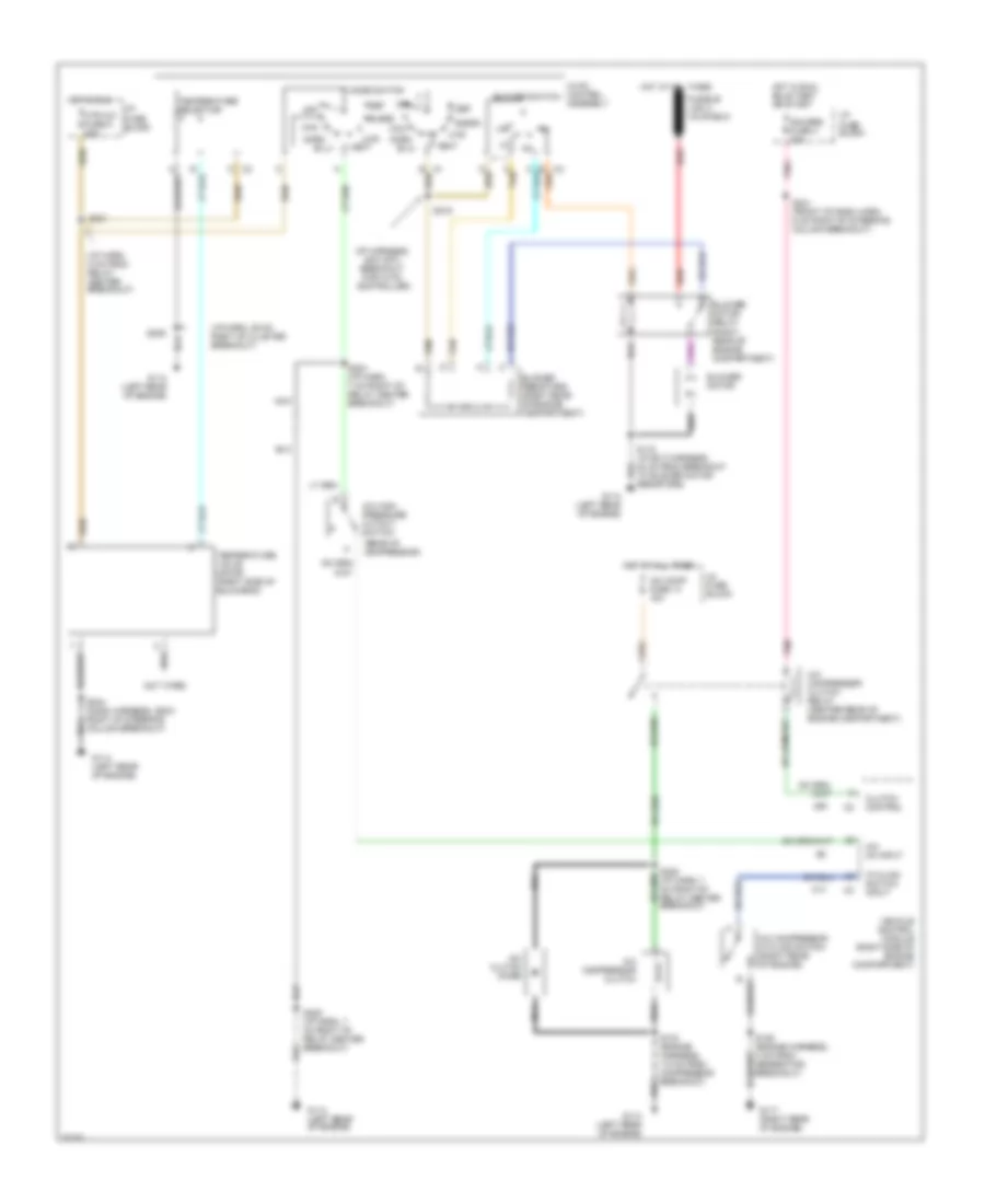
A/C Wiring Diagram for Chevrolet Blazer 1997
List of elements for A/C Wiring Diagram for Chevrolet Blazer 1997:
- (cut wire)
- (i/p harn, 39 cm right of cluster breakout)
- (i/p harn, 5 cm from relay center breakout)
- (i/p harness, 6cm into breakout for hvac controller)
- (rear of compressor)
- A tan
- A/c clutch diode
- A/c comp fuse 14 10a
- A/c compressor clutch
- A/c compressor clutch relay (center rear of engine compartment)
- A/c compressor cycling switch (right rear of engine)
- A/c high pressure cutout switch
- A/c on input
- Bi-lv
- Blend
- Blower motor
- Blower motor relay (right rear of engine compartment)
- Blower resistors (right rear of engine compartment)
- Blower switch
- Clutch control
- Cycling switch input
- Def
- G114 (left rear of engine)
- G117 (right rear of engine)
- Gauges fuse 4 20a
- Hot at all times
- Hot in run
- Hot in run, bulb test or start
- Htr
- Htr a/c fuse 6 20a
- Hvac control assembly
- I/p fuse block
- Max
- Mode switch
- Nca
- Norm
- Off
- Pnk
- Red
- S103 (engine harness, 7.5 cm from compressor breakout)
- S106 (engine harness, 4 cm from generator breakout)
- S118 (i/p ext harness, 40 cm from breakout to blower motor resistors)
- S209
- S215
- S221
- S224 (i/p harn, 7 cm right of relay center breakout)
- S225 (i/p harn, 7 cm right of relay center breakout)
- S241 (front of dash harn, 6 cm right of steering column breakout)
- S244 (dash harness, 26cm right of steering column breakout)
- Tan
- Temperature selector
- Temperature valve motor (right side of bulkhead)
- Vehicle control module (right side of engine compartment)
- Vent
 English