AIR CONDITIONING
Compressor Wiring Diagram for Chevrolet Chevy Express H1500 2007

List of elements for Compressor Wiring Diagram for Chevrolet Chevy Express H1500 2007:
- (6.6l)
- (except 6.6l)
- 2006: diesel
- A/c compressor clutch (4.3l : at left front of eng, 6.6l : top front of eng, except 4.3l & 6.6l: at lower right front of eng)
- A/c fuse 32 10a
- A/c high pressure switch (6.6l: on rear of a/c compressor, except 6.6l: on rear portion of a/c compressor)
- A/c low pressure switch (on side of accumulator)
- A/c relay 54
- Bi-lev
- Body fuse block (under left front seat)
- Clutch rly ctrl
- D12
- Def
- F12
- G102 (left front lower side of engine block)
- G102 (on left rear of engine)
- Gasoline
- Heat
- Heat/def
- Hot at all times
- Hot in run
- Hot in run or start
- Hvac control assembly
- Hvac fuse 10 20a
- Ign e fuse 22 10a
- Low press sig
- Max
- Norm
- Off
- Powertrain control module (pcm) (on left inner fender, in engine compt) (gasoline) engine control module (ecm) (left side of engine compt) (diesel)
- Request sig
- S102
- Underhood fuse block (on left side of engine compt)
- Vent
Heater Wiring Diagram for Chevrolet Chevy Express H1500 2007
List of elements for Heater Wiring Diagram for Chevrolet Chevy Express H1500 2007:
- (6.6l)
- (except 6.6l)
- (on bottom of left "b" pillar) g347
- (on left rear of
- (rear a/c harn, 24 cm from rear blower motor resistor breakout)
- (rear hvac harn, 13 cm from auxiliary blower motor connector breakout)
- (rear hvac harn, 20 cm from auxiliary blower motor connector breakout)
- (w/ rear auxiliary heater) (w/ rear hvac)
- Air temperature actuator (behind right side of dash, on hvac)
- Auxiliary blower motor (if equipped (left rear of passenger
- Auxiliary blower motor resistor (if equipped) (on left rear of
- Auxiliary blower motor switch (if equipped)
- Auxiliary high speed blower motor relay (if equipped) (on left rear of
- Auxiliary low speed blower motor relay (if equipped)
- Auxiliary medium speed blower motor relay (if equipped) (on left rear of
- Bi-lev
- Blow fuse 51 40a
- Blower motor (right rear of engine compt, on evaporator case)
- Blower motor resistor assembly (right rear of engine compt)
- Body fuse block (below left front seat)
- Compt, on auxiliary hvac assembly)
- Def
- F10
- G102 (left front lower side of engine block)
- G102 (on left rear of engine)
- G304 (behind right kick panel)
- G401 (on top of right "d" pillar)
- Heat
- Heat/def
- Hot at all times
- Hot in run
- Hvac 1 fuse 9 10a
- Hvac control assembly
- Hvac fuse 20a
- Interior lights system
- Med
- Off
- Passenger compt, on auxiliary hvac assembly)
- Rr blower fuse 13 30a
- S102
- S249
- S401 s411
- S405
- S412
- S413
- Splice pack sp347
- Tan
- Underhood fuse block (on left side of engine compt)
- Vent
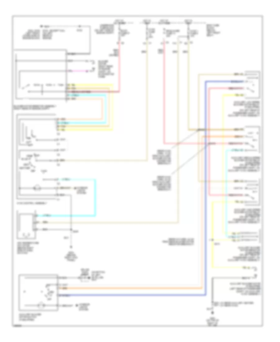
Manual A/C Wiring Diagram, Cargo Van (1 of 3) for Chevrolet Chevy Express H1500 2007
List of elements for Manual A/C Wiring Diagram, Cargo Van (1 of 3) for Chevrolet Chevy Express H1500 2007:
- (6.6l)
- (behind right kick panel) g304
- (behind right side
- (diesel)
- (except 6.6l)
- A/c high pressure switch (6.6l: on rear of a/c compressor, except 6.6l: on rear portion of a/c compressor)
- Auxiliary air temperature actuator (on auxiliary hvac assembly)
- Auxiliary mode actuator (left rear of passenger compt)
- Battery
- Bi-lev
- Blow fuse 51 40a
- Blower motor (right rear of engine compt)
- Blower motor resistor assembly (at right rear of engine compt, on evaporator case)
- Body fuse block (under left front seat)
- C2 a
- C2 c
- Def
- Defogger system
- F10
- Front auxiliary hvac control assembly (if equipped)
- G102 (left front lower side of engine block)
- G102 (on left rear of engine)
- G347 (on bottom of left "b" pillar)
- G401 (on top of right "d" pillar)
- Ground
- Heat
- Heat/def
- Hot at all times
- Hot in run
- Hvac 1 fuse 9 10a
- Hvac control assembly
- Hvac fuse 20a
- Ing 3
- Interior lights system
- Logic
- Max
- Med
- Norm
- Of dash, on hvac) air temperature actuator
- Off
- R defog ind
- Rear blwr fuse 13 30a
- S102
- S249
- S314
- S411
- Tan
- Underhood fuse block (on left side of engine compt)
- Vacuum pump (right front of engine compt, under battery) a
- Vent
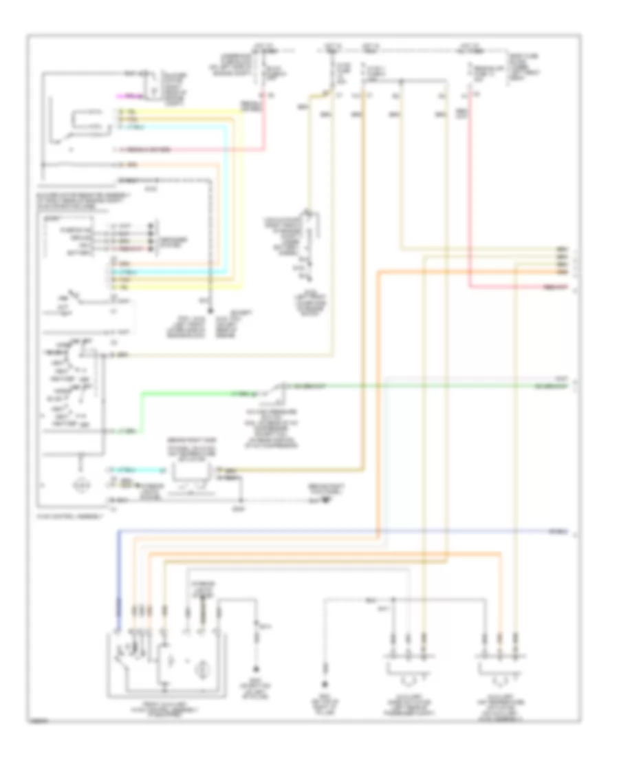
Manual A/C Wiring Diagram, Cargo Van (2 of 3) for Chevrolet Chevy Express H1500 2007
List of elements for Manual A/C Wiring Diagram, Cargo Van (2 of 3) for Chevrolet Chevy Express H1500 2007:
- (6.6l)
- (except 6.6l)
- (on left rear of
- (provisional)
- (rear hvac harn, 13 cm from auxiliary blower motor connector breakout)
- (top of right "d" pillar) g401
- (w/ rv upfitter
- (w/ rv upfitter option:
- (w/ rv upfitter option: body harn, 22 cm from c308 breakout) (w/o rv upfitter option: body harn, 41 cm from c304 breakout)
- A/c compressor clutch (4.3l: at left front of eng, 4.8l, 5.3l & 6.0l: at lower right front of eng, 6.6l: top front of eng)
- A/c fuse 32 10a
- A/c low pressure switch (on side of accumulator)
- A/c relay 54
- Auxiliary blower motor (if equipped) (on auxiliary hvac)
- Auxiliary blower motor resistor (if equipped)
- Auxiliary high speed blower motor relay (if equipped)
- Auxiliary low speed blower motor relay (if equipped)
- Auxiliary medium speed blower motor relay (if equipped)
- Body harn, 22 cm from c308 breakout) (w/o rv upfitter option: body harn, 5 cm from c304 breakout)
- C319
- Clutch rly ctrl
- D12
- Diesel
- F12
- G102 (left front lower side of engine block)
- G102 (on left rear of engine)
- Gasoline
- Hot at all times
- Hot in run or start
- Ign e fuse 22 10a
- Low press sig
- Option: body harn, 32 cm from c308 breakout) (w/o rv upfitter option: body harn, 31 cm from c304 breakout)
- Passenger compt, on auxiliary hvac assembly)
- Powertrain control module (pcm) (on left front inner fender) (gasoline) engine control module (ecm) (left side of engine compt) (diesel)
- Req sig
- S102
- S308
- S310
- S311
- S405
- S411
- S412 (rear hvac harn, 20 cm from auxiliary blower motor connector breakout)
- S413 (rear a/c harn, 24 cm from aux blower motor breakout)
- Underhood fuse block (on left side of engine compt)
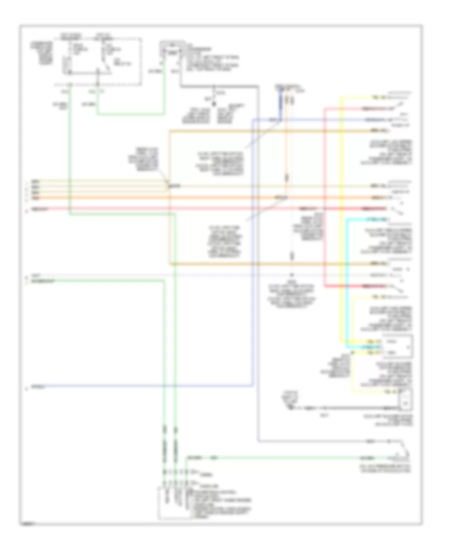
Manual A/C Wiring Diagram, Cargo Van (3 of 3) for Chevrolet Chevy Express H1500 2007
List of elements for Manual A/C Wiring Diagram, Cargo Van (3 of 3) for Chevrolet Chevy Express H1500 2007:
- (under left side of dash) data link connector (dlc)
- 5v ref
- Combustion sensor
- Coolant heater (diesel)
- Coolant heater air temperature sensor
- Coolant heater blower
- Coolant heater fuel pump (attached to left inner frame rail, near the fuel pump assembly)
- Coolant heater glow plug
- Coolant sensor
- Engine control module (ecm) (left side of engine compt)
- Foh/ecm/ tcm batt fuse 2 20a
- Fuel pump
- G400 (on inner left rear frame rail)
- Glow plug control module (gpcm) (turbo: left rear of eng, except turbo: top rear of eng)
- Grd
- Hot at all times
- Low ref
- Nca
- Overheat sensor
- Red
- S402
- Serial +
- Serial -
- Splice pack sp250 (in dash harn, approximately 20 cm from underhood pass through grommet)
- Tan
- Transmission control module (tcm) (left front of engine compt)
- Underhood fuse block (on left side of engine compt)
- Volt
- Volt +
- W/ auxiliary heater
- W/o auxiliary heater
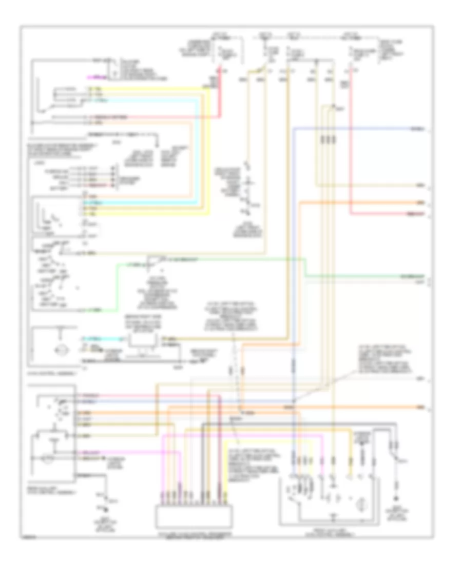
Manual A/C Wiring Diagram, Passenger Van (1 of 3) for Chevrolet Chevy Express H1500 2007
List of elements for Manual A/C Wiring Diagram, Passenger Van (1 of 3) for Chevrolet Chevy Express H1500 2007:
- (6.6l)
- (behind right kick panel) g304
- (behind right side
- (diesel)
- (except 6.6l)
- (w/ rv upfitter option:
- (w/ rv upfitter option: in upfitter hvac control harn, 19 cm from c303 breakout) (w/o rv upfitter option: in front headliner harn, 42 cm from c304 breakout)
- (w/ rv upfitter option: in upfitter hvac control harn, 64 cm from c303 breakout) (w/o rv upfitter option: in front headliner harn, 11 cm from c304 breakout)
- A/c high pressure switch (6.6l: on rear of a/c compressor, except 6.6l: on rear portion of a/c compressor)
- Auxiliary hvac control processor (center front of headliner)
- Battery
- Bi-lev
- Blow fuse 51 40a
- Blower motor (on right rear of engine compt, on evaporator case)
- Blower motor resistor assembly (at right rear of engine compt, on evaporator case)
- Body fuse block (under left front seat)
- C1 g
- C2 a
- C2 c
- Def
- Defogger system
- F10
- Front auxiliary hvac control assembly
- G102 (left front lower side of engine block)
- G102 (on left rear of engine)
- G347 (on bottom of left "b" pillar)
- Ground
- Heat
- Heat/def
- Hot at all times
- Hot in run
- Hvac 1 fuse 9 10a
- Hvac control assembly
- Hvac fuse 20a
- In upfitter hvac control harn, 39 cm from c303 breakout) (w/o rv upfitter option: in front headliner harn, 31 cm from c304 breakout)
- Ing 3
- Interior lights system
- Logic
- Max
- Med
- Norm
- Of dash, on hvac) air temperature actuator
- Off
- R defog ind
- Rear
- Rear auxiliary hvac control assembly
- Rr blower fuse 13 30a
- S102
- S249
- S305
- S306
- S307
- S314
- S354
- Tan
- Tan e
- Underhood fuse block (on left side of engine compt)
- Vacuum pump (right front of engine compt, under battery) a
- Vent
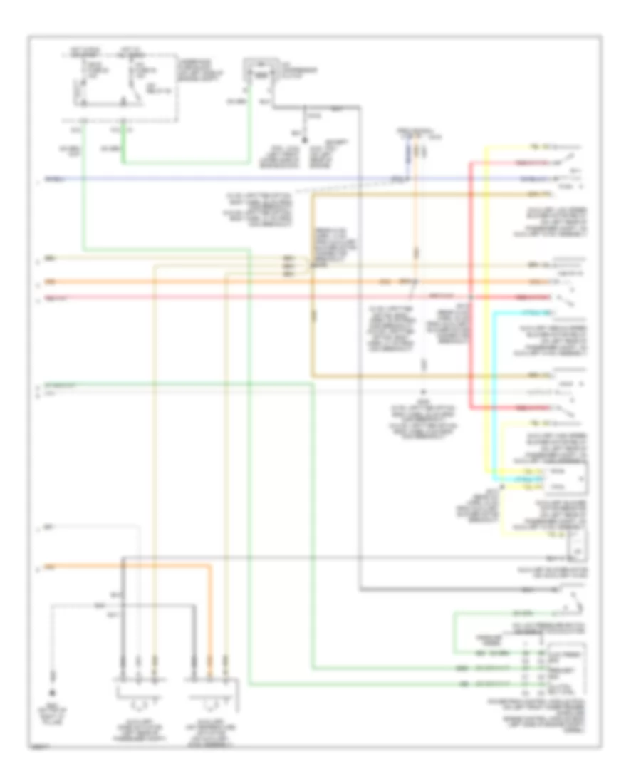
Manual A/C Wiring Diagram, Passenger Van (2 of 3) for Chevrolet Chevy Express H1500 2007
List of elements for Manual A/C Wiring Diagram, Passenger Van (2 of 3) for Chevrolet Chevy Express H1500 2007:
- (6.6l)
- (except 6.6l)
- (on left rear of
- (provisional)
- (rear hvac harn, 13 cm from auxiliary blower motor connector breakout) s405
- (w/ rv upfitter
- (w/ rv upfitter option:
- (w/ rv upfitter option: body harn, 22 cm from c308 breakout) (w/o rv upfitter option: body harn, 41 cm from c304 breakout)
- A/c compressor clutch
- A/c fuse 32 10a
- A/c low pressure switch (on side of accumulator)
- A/c relay 54
- Auxiliary air temperature actuator (on auxiliary hvac assembly)
- Auxiliary blower motor (on auxiliary hvac)
- Auxiliary blower motor resistor
- Auxiliary high speed blower motor relay
- Auxiliary low speed blower motor relay
- Auxiliary medium speed blower motor relay
- Auxiliary mode actuator (left rear of passenger compt)
- Body harn, 22 cm from c308 breakout) (w/o rv upfitter option: body harn, 5 cm from c304 breakout)
- C319
- Clutch rly ctrl c2
- D12
- F12
- G102 (left front lower side of engine block)
- G102 (on left rear of engine)
- G401 (on top of right "d" pillar)
- Gasoline diesel
- Hot at all times
- Hot in run or start
- Ign e fuse 22 10a
- Low press sig c2
- Option: body harn, 32 cm from c308 breakout) (w/o rv upfitter option: body harn, 31 cm from c304 breakout)
- Passenger compt, on auxiliary hvac assembly)
- Powertrain control module (pcm) (on left front inner fender) (gasoline) engine control module (ecm) (left side of engine compt) (diesel)
- Request sig c2
- S102
- S308
- S310
- S311
- S411
- S412 (rear hvac harn, 20 cm from auxiliary blower motor connector breakout)
- S413 (rear a/c harn, 24 cm from auxiliary blower motor breakout)
- Underhood fuse block (on left side of engine compt)
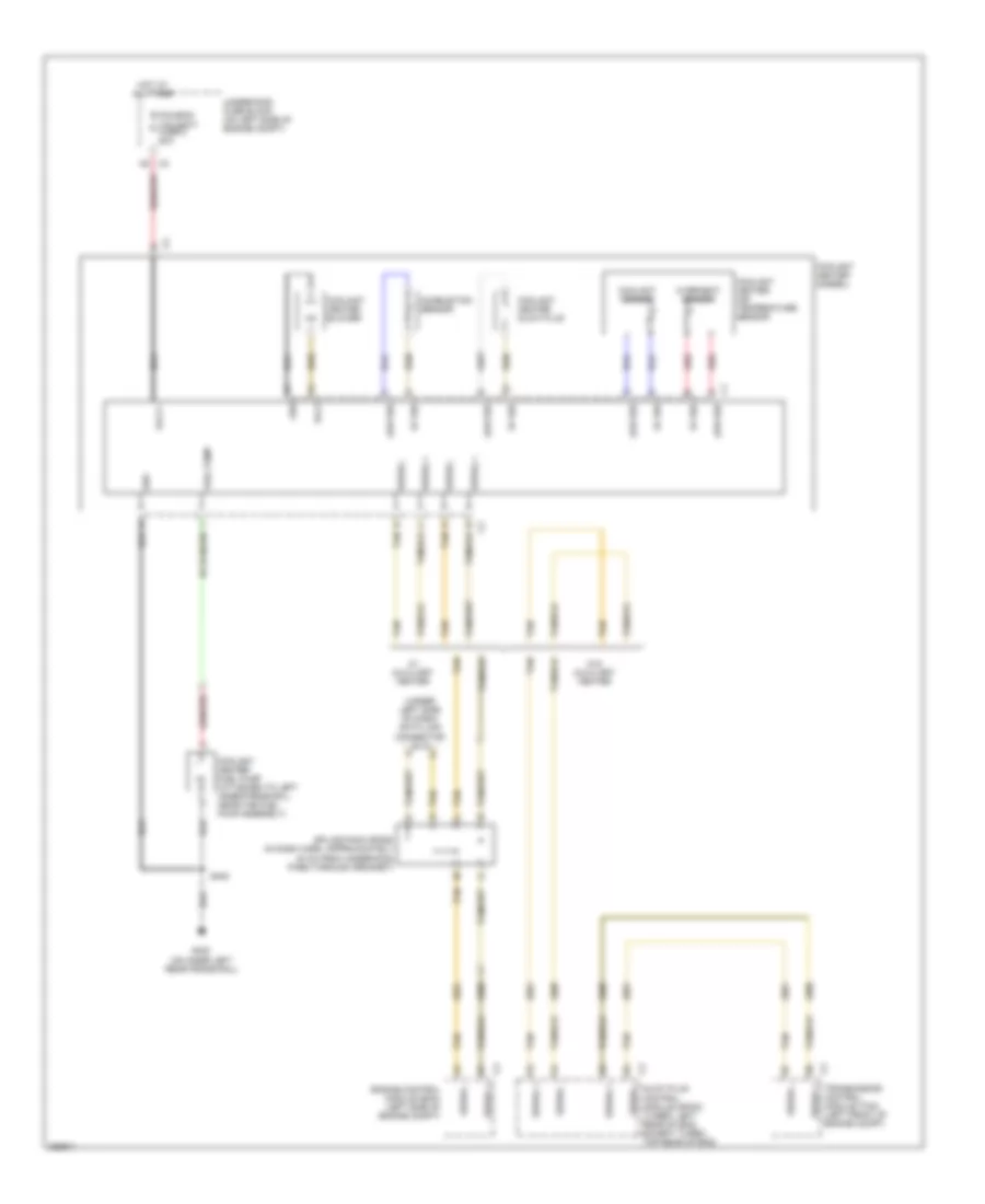
Manual A/C Wiring Diagram, Passenger Van (3 of 3) for Chevrolet Chevy Express H1500 2007
List of elements for Manual A/C Wiring Diagram, Passenger Van (3 of 3) for Chevrolet Chevy Express H1500 2007:
- (under left side of dash) data link connector (dlc)
- 5v ref
- Combustion sensor
- Coolant heater (diesel)
- Coolant heater air temperature sensor
- Coolant heater blower
- Coolant heater fuel pump (attached to left inner frame rail, near the fuel pump assembly)
- Coolant heater glow plug
- Coolant sensor
- Engine control module (ecm) (left side of engine compt)
- Foh/ecm/ tcm batt fuse 2 20a
- Fuel pump
- G400 (on inner left rear frame rail)
- Glow plug control module (gpcm) (turbo: left rear of eng, except turbo: top rear of eng)
- Grd
- Hot at all times
- Low ref
- Nca
- Overheat sensor
- Red
- S402
- Serial +
- Serial -
- Splice pack sp250 (in dash harn, approximately 20 cm from underhood pass through grommet)
- Tan
- Transmission control module (tcm) (left front of engine compt)
- Underhood fuse block (on left side of engine compt)
- Volt
- Volt +
- W/ auxiliary heater
- W/o auxiliary heater