AIR CONDITIONING
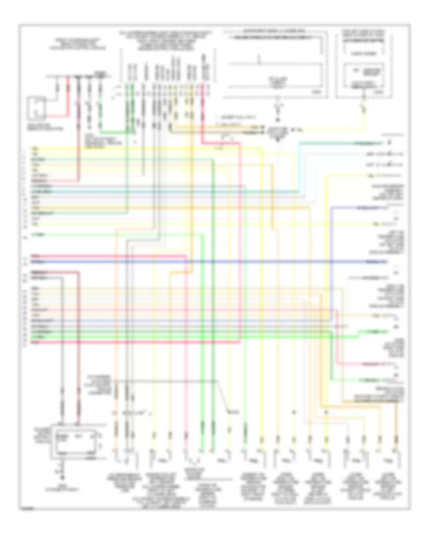
Automatic A/C Wiring Diagram (1 of 2) for Chevrolet Corvette 2011

List of elements for Automatic A/C Wiring Diagram (1 of 2) for Chevrolet Corvette 2011:
- A/c comp fuse 15 10a
- A/c comp relay 35
- A/c compressor clutch (right front of engine block)
- A/c off switch
- Bat
- Blower ctrl
- Blower speed switch
- Body control module (bcm) (mounted on toe board, in right footwell)
- Charge air coolant pump (right front of engine compt)
- Coolfan fuse 25 60a
- Defog rly ctrl
- Defogger system
- Defrost frost
- Defrost ind
- Defrost switch
- Dr ctrl a
- Dr ctrl b
- Drv htd st sig
- E1 x2
- E10
- F13
- F14
- G102 (on top of right frame rail, ground for jp102)
- G202 (at base of right)
- Gnd
- H13
- H14
- Hot at all times
- Hot w/ run/ crnk relay energized
- Hvac control module (center of dash, under radio)
- Hvac fuse 28 40a
- Hvac/ pwr snd fuse 10a
- Ign
- Ign 1 voltage
- Inclr pump/elsd fuse 32 (6.2l (vin t)) 30a
- Inclr pump/elsd relay
- Interior lights system
- Isrvm/ hvac fuse 10a
- J102
- J197
- J216
- J231
- Lamp ctrl
- Left air tempe- rature switch
- Light sens sig
- Logic
- Low ref
- Mirrors & shift interlock systems
- Mode ctrl
- Mode switch
- Mtr spd ctrl
- Off ctrl
- Pass htd st sig
- Pnk
- Powertrain ign 1 relay 44
- Recirc ctrl
- Recirculation switch
- Right air tempe- rature switch
- Seats system
- Sens sig
- Serial data
- Speed ctrl
- Sply voltage
- Sply voltage 4
- Sunload sig
- Tan
- Temp ctrl
- Temp ctrl sig
- Underhood fuse block (on right side of engine compt)
- X1 c10
- X4 d8
Automatic A/C Wiring Diagram (2 of 2) for Chevrolet Corvette 2011
List of elements for Automatic A/C Wiring Diagram (2 of 2) for Chevrolet Corvette 2011:
- (6.2l supercharged: right side of engine compt) (6.2l except supercharged & 7.0l: behind right front fender, between wheelhouse & dash panel) engine control module (ecm)
- (front of engine compt, rear of radiator) cooling fan control module
- (top left side of dash) head up display (hud)
- 5v ref
- 6.2l (vin t)
- A/c refrigerant pressure sensor (on a/c high pressure line)
- Ambient air temperature sensor (on radiator support, at right front of engine)
- Aspirator blower motor
- Bat
- Blower motor control module
- Check gages
- Computer data lines system
- Cooling fan (rear of radiator)
- Driver information center (dic) display
- Engine coolant temperature (ect) sensor (6.2l supercharged: front of left cylinder head) (6.2l except supercharged & 7.0l: in front left side of left cylinder head)
- Except 6.2l (vin t)
- G102 (on top of right frame rail, ground for jp102)
- G202 (at base of right)
- Gnd
- Hud class 2 serial data
- Hud message center
- Ign
- Ignition 1
- Inside air temperature sensor (right of steering column)
- Instrument panel cluster (ipc)
- Ipc class 2 serial data
- J242
- Left air temperature actuator (on left side of hvac module assembly)
- Logic
- Low ref
- Lower left air temperature sensor (in left middle of hvac module)
- Lower right air temperature sensor (in right middle of hvac module)
- Message request
- Mode actuator (right side of hvac module)
- Module connector)
- Nca
- Pnk
- Recirculation actuator (mounted to right side of blower motor assembly)
- Red
- Right air temperature actuator (on right side of hvac module assembly)
- Rly ctrl
- Rly ctrl coolant pumr
- Sens sig
- Serial data +
- Serial data -
- Speed ctrl
- Sunload sensor assembly (on top left center of dash)
- Tan
- Upper left air temperature sensor (in left center of dash, in hvac air flow duct)
- Upper right air temperature sensor (in upper right of dash, in hvac air flow duct)
- X186
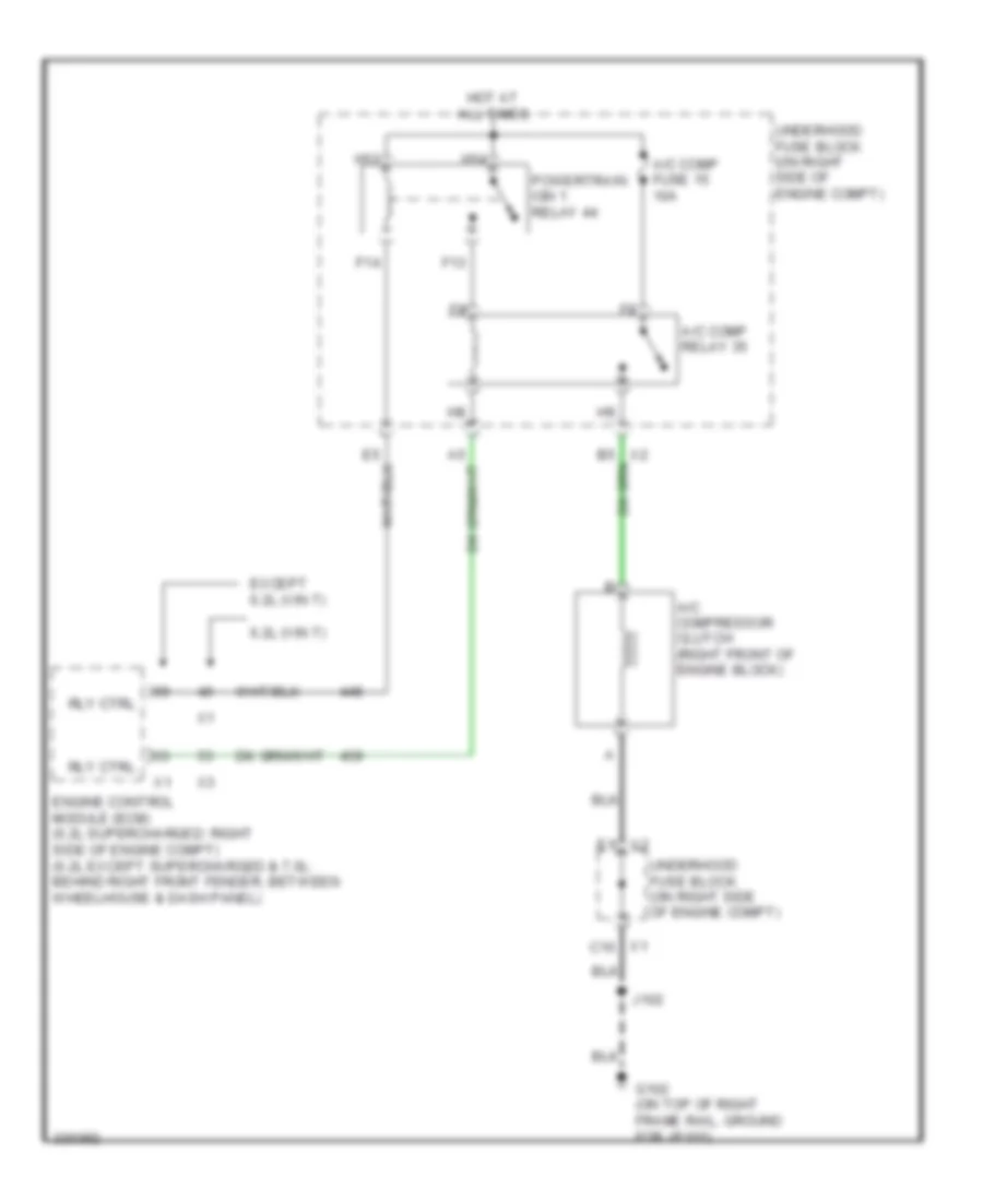
Compressor Wiring Diagram for Chevrolet Corvette 2011
List of elements for Compressor Wiring Diagram for Chevrolet Corvette 2011:
- 6.2l (vin t)
- A/c comp fuse 15 10a
- A/c comp relay 35
- A/c compressor clutch (right front of engine block)
- E1 x2
- Engine control module (ecm) (6.2l supercharged: right side of engine compt) (6.2l except supercharged & 7.0l: behind right front fender, between wheelhouse & dash panel)
- Except 6.2l (vin t)
- F13
- F14
- G102 (on top of right frame rail, ground for jp102)
- H13
- H14
- Hot at all times
- J102
- Powertrain ign 1 relay 44
- Rly ctrl
- Underhood fuse block (on right side of engine compt)
- X1 c10