AIR CONDITIONING
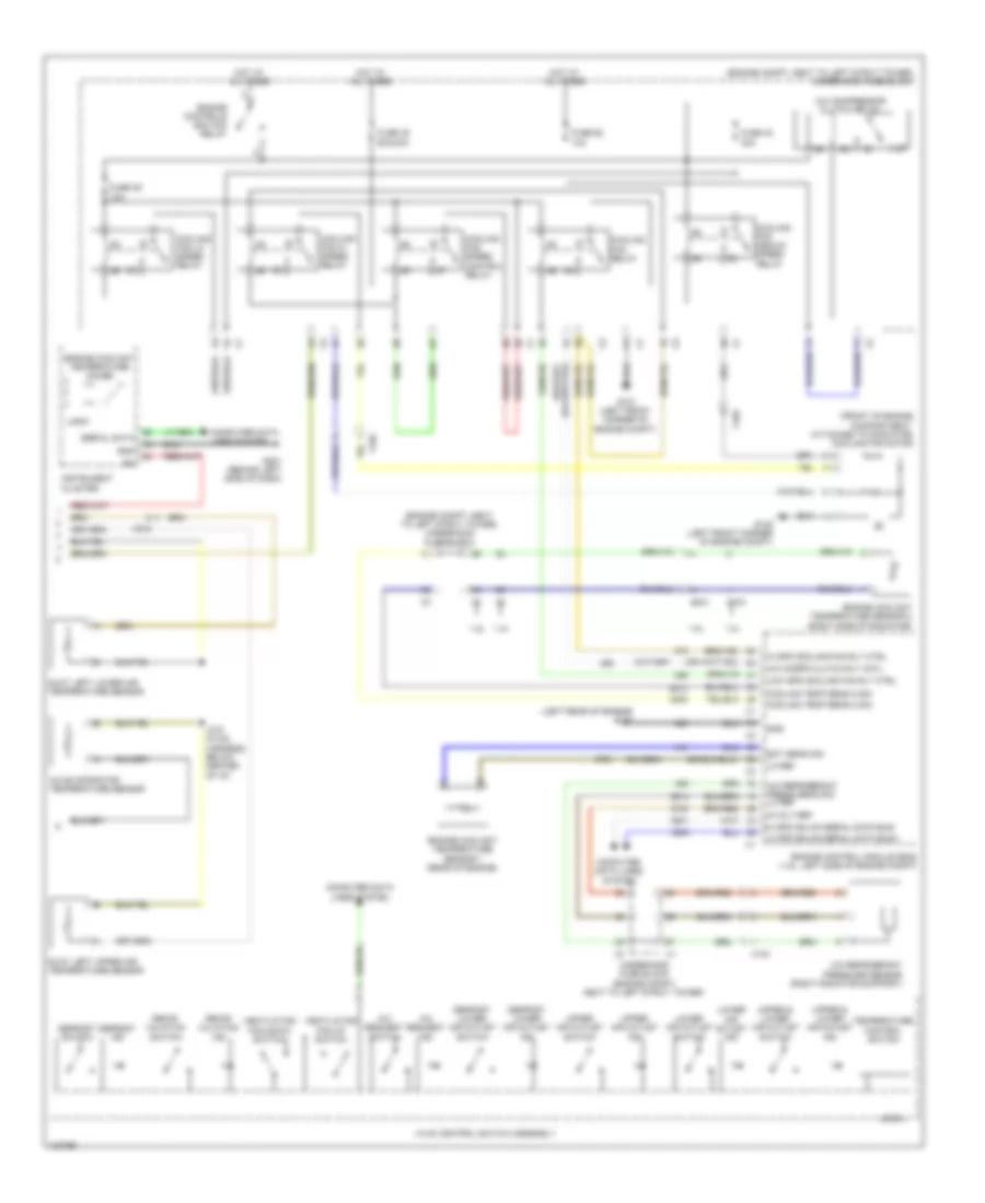
Automatic A/C Wiring Diagram (1 of 2) for Chevrolet Cruze LS 2013

List of elements for Automatic A/C Wiring Diagram (1 of 2) for Chevrolet Cruze LS 2013:
- (behind center of dash) g202
- (front center of dash) ambient light sunload sensor
- (hvac harness, below center of i/p)
- (left rear of engine) g114
- (rear of engine compt) air quality sensor
- (right front corner of engine compt) g104
- 5-volt ref
- 5v ref
- A/c compressor (1.4l: lower left front of engine) (1.8l: left front of engine)
- A/c compressor clutch
- A/c compressor solenoid valve
- Air quality sens sig
- Air recirculation door motor (on hvac module, above blower motor)
- Air temp dr ctrl
- Air temperature door actuator (left side of hvac module)
- Anti- theft system
- B+ blwr mtr fan rly x2
- Batt +
- Blower motor (under right side of dash)
- Blower motor control module (on hvac module, left of blower motor)
- Blwr mtr spd ctrl
- Blwr mtr spd rly
- Computer data lines system
- Defogger system
- Ele varbl displment ctrl
- Ele varbl displment sply
- Evap core temp sens sig
- Fuse 15a
- Fuse 40a
- Fuse 5a
- Fuse 7.5a
- G202 (behind center of dash)
- Gnd
- Gnd b+ x1
- Head- lights system
- Hot at all times
- Hot w/ ignition main relay energized
- Humidity sens sig
- Humidity temp sens sig
- Hvac control module (center of dash)
- Ign volt
- Inside air temp sens sig
- Instrument panel fuse block (behind left end of dash)
- J124
- J213 (instrument panel harness, 15 cm from i/p cluster breakout)
- J271
- J309
- Logic
- Low ref
- Low spd gmlan ser data
- Mode door actuator (left side of hvac module)
- Mode dr stepper mtr ctrl
- Nca
- Network bus 9
- Power distribution system
- Rear defog rly ctrl
- Recirculation dr ctrl
- Red
- Sens low ref
- Solar sens drv sig
- Solar sens pul sply volt
- Underhood fuse block (in engine compt, next to left strut tower)
- Upp lh air temp sens sig
- Upper air temp sens sig
- Windscreen temp sens sig
- Windshield temperature & inside moisture sensor (top center of windshield)
- X100
- X190
- X200
- X210
Automatic A/C Wiring Diagram (2 of 2) for Chevrolet Cruze LS 2013
List of elements for Automatic A/C Wiring Diagram (2 of 2) for Chevrolet Cruze LS 2013:
- (engine compt, next to left strut tower) underhood fuse block
- (front of engine compartment, attached to radiator) cooling fan motor
- (left rear of engine) g114
- 1.4l
- 1.8l
- 5-volt ref
- A/c compr clutch rly cotl
- A/c compressor clutch relay
- A/c evaporator temperature sensor
- A/c refrigerant press sens sig lo ref
- A/c refrigerant pressure sensor (right radiator support)
- A/c request ind
- A/c request switch
- Computer data lines system
- Cooling fan hi speed relay
- Cooling fan lo speed relay
- Cooling fan medium speed relay
- Cooling fan relay
- Cooling fan speed control relay
- Cooling temp sens 2 sig
- Defrost ind
- Defrost lower air outlet ind
- Defrost lower air outlet switch
- Defrost switch
- Duct left lower air temperature sensor
- Duct left upper air temperature sensor
- Ect sens sig
- Engine control module (ecm) (1.8l: left side of engine compt)
- Engine controls ignition relay
- Engine coolant temperature gauge
- Engine coolant temperature sensor 1 (rear of engine)
- Engine coolant temperature sensor 2 (right side of radiator)
- Fuse 42 30a
- Fuse 45 60a/40a
- Fuse 46 10a
- Fuse 62 10a
- G101 (left front corner of engine compt)
- G105 (left front corner of engine compt)
- G201 (behind left side of dash)
- Gnd
- Hi spd cooling fan rly ctrl
- Hi spd gmlan serial data bus+
- Hi spd gmlan serial data bus-
- Hot at all times
- Hvac control switch assembly
- Instrument cluster
- J272 (hvac harness, below center of i/p)
- Lo ref
- Logic
- Low spd cooling fan rly ctrl
- Lower air outlet ind
- Lower air outlet switch
- Recir- culation ind
- Recir- culation switch
- Serial data
- Temperature control switch
- Underhood fuse block (engine compt, next to left strut tower)
- Upper & lower air outlet ind
- Upper & lower air outlet switch
- Upper air outlet ind
- Upper air outlet switch
- Ventilating fan down switch
- Ventilating fan up switch
- X102
- X104
- X212
Manual A/C Wiring Diagram (1 of 2) for Chevrolet Cruze LS 2013
List of elements for Manual A/C Wiring Diagram (1 of 2) for Chevrolet Cruze LS 2013:
- (behind center of dash) g202
- (hvac harness, below center of i/p)
- (left rear of engine) g114
- 5-volt ref
- A/c compressor (1.4l: lower left front of engine) (1.8l: left front of engine)
- A/c compressor clutch
- A/c compressor solenoid valve
- Air recirculation door motor (on hvac module, above blower motor)
- Air temp dr ctrl
- Air temperature door actuator (left side of hvac module)
- B+ blwr mtr fan rly x2
- Batt +
- Blower motor (under right side of dash)
- Blower motor control module (on hvac module, left of blower motor)
- Blwr mtr spd ctrl
- Blwr mtr spd rly
- Computer data lines system
- Defogger system
- Ele varbl displment ctrl
- Ele varbl displment sply
- Evap core temp sens sig
- Fuse 15a
- Fuse 40a
- Fuse 5a
- G202 (behind center of dash)
- Gnd
- Hot at all times
- Hot w/ ignition main relay energized
- Hvac control module (center of dash)
- Ign volt
- Instrument panel fuse block (behind left end of dash)
- J124
- J271
- J309
- Low spd gmlan ser data
- Mode door actuator (left side of hvac module)
- Mode dr stepper mtr ctrl
- Nca
- Network bus 9
- Power distribution system
- Rear defog rly ctrl
- Recirculation dr ctrl
- Red
- Sens low ref
- Underhood fuse block (engine compt, next to left strut tower)
- X190
- X200
Manual A/C Wiring Diagram (2 of 2) for Chevrolet Cruze LS 2013
List of elements for Manual A/C Wiring Diagram (2 of 2) for Chevrolet Cruze LS 2013:
- (engine compt, next to left strut tower) underhood fuse block
- (front of engine compartment, attached to radiator) cooling fan motor
- (left rear of engine) g114
- 1.4l
- 1.8l
- 5-volt ref
- A/c compr clutch rly cotl
- A/c compressor clutch relay
- A/c evaporator temperature sensor
- A/c refrigerant press sens sig lo ref
- A/c refrigerant pressure sensor (right radiator support)
- A/c request ind
- A/c request switch
- Computer data lines system
- Cooling fan hi speed relay
- Cooling fan lo speed relay
- Cooling fan medium speed relay
- Cooling fan relay
- Cooling fan speed control relay
- Cooling temp sens 2 sig
- Defrost ind
- Defrost lower air outlet ind
- Defrost lower air outlet switch
- Defrost switch
- Ect sens sig
- Engine control module (ecm) (1.8l: left side of engine compt)
- Engine controls ignition relay
- Engine coolant temperature (ect) sensor 1 (rear of engine)
- Engine coolant temperature gauge
- Engine coolant temperature sensor 2 (right side of radiator)
- Fuse 42 30a
- Fuse 45 60a/40a
- Fuse 46 10a
- Fuse 62 10a
- G101 (left front corner of engine compt)
- G105 (left front corner of engine compt)
- G201 (behind left side of dash)
- Gnd
- Hi spd cooling fan rly ctrl
- Hi spd gmlan serial data bus+
- Hi spd gmlan serial data bus-
- Hot at all times
- Hvac control switch assembly
- Instrument cluster
- Lo ref
- Logic
- Low spd cooling fan rly ctrl
- Lower air outlet ind
- Lower air outlet switch
- Recir- culation ind
- Recir- culation switch
- Serial data
- Temperature control switch
- Underhood fuse block (engine compt, next to left strut tower)
- Upper & lower air outlet ind
- Upper & lower air outlet switch
- Upper air outlet ind
- Upper air outlet switch
- Ventilating fan down switch
- Ventilating fan up switch
- X102
- X104