AIR CONDITIONING
Compressor Wiring Diagram for Chevrolet Impala LS 2003

List of elements for Compressor Wiring Diagram for Chevrolet Impala LS 2003:
- +5v reference
- A/c compressor clutch
- A/c compressor relay
- A/c press signal
- A/c refrigerent pressure sensor (left side of engine compt, on liquid line)
- A/c rly fuse 10a
- Comp control
- Computer data lines system
- E11
- F11
- G113 (3.8l) g117 (3.4l) (on transaxle stud, near starter)
- Hot at all times
- Hot in run
- Low reference
- Nca
- Pnk
- Powertrain control module (left front side of engine compt, in air cleaner assembly)
- S158
- Serial data
- Underhood junction block (bottom) (forward of right front strut tower)
- Underhood junction block (top) (forward of right front strut tower)
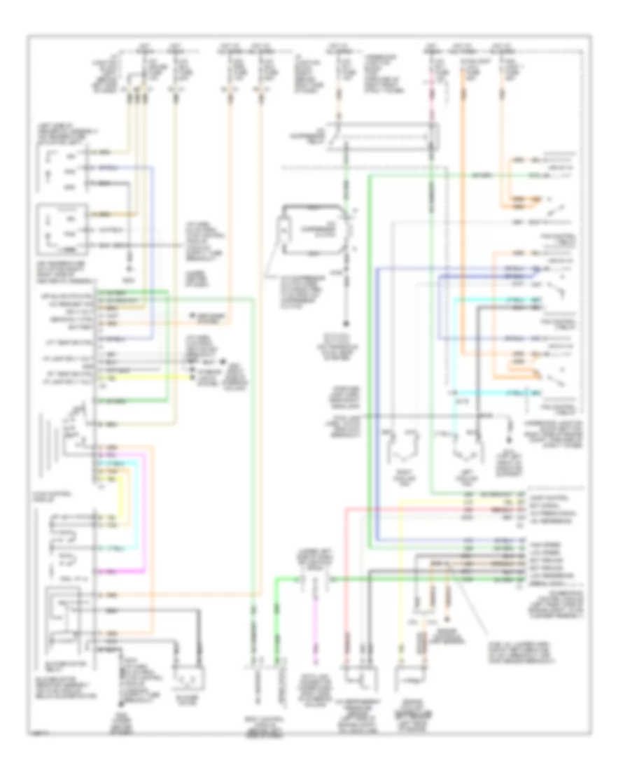
Manual A/C Wiring Diagram for Chevrolet Impala LS 2003
List of elements for Manual A/C Wiring Diagram for Chevrolet Impala LS 2003:
- (forward lamp harn, near right headlamp)
- (fuel inj jumper harn, midway between fuel inj no 3 breakout and (map) sensor breakout)
- (fwd lamp harn, 18.5 cm from g101 breakout)
- (i/p harn, 8 cm from ignition sw breakout) s229
- (left side of heater-a/c assembly) air temperature actuator (left)
- (under center of dash)
- (under left side of dash) splice pack sp205
- +5v reference
- 3.4l
- 3.8l
- A/c blo fuse 20a
- A/c blo fuse 25a
- A/c compressor clutch
- A/c compressor clutch diode (in wiring harn, 10 cm from a/c compressor clutch)
- A/c compressor relay
- A/c cruise fuse 10a
- A/c press signal
- A/c refrigerent pressure sensor (left side of engine compt, on liquid line)
- A/c request
- A/c request sig
- A/c rly fuse 10a
- Air temperature actuator (right) (right side of heater-a/c assembly)
- B10
- Battery
- Blower motor
- Blower motor relay
- Blower motor resistor assembly (on hvac module, below blower motor)
- Body control module (behind left side of dash)
- C1 f6
- C10
- Comp control
- D4 c1
- Data link connector (under dash, right side of steering column)
- Defog rly ctrl
- Defogger system
- Dic/ rke fuse 10a
- E11
- Ect ground
- Ect signal
- Engine controls (map sensor)
- Engine coolant temperature (ect) sensor (left rear of engine)
- F11
- F5 c1
- Fan cont 1 fuse 25a
- Fan cont 2 & 3 fuse 25a
- Fan control 1 relay
- Fan control 2 relay
- Fan control 3 relay
- G101 (top left front of radiator support)
- G113 (3.8l) g117 (3.4l) (on transaxle stud, near starter)
- G201 (right side of steering column)
- G202
- G202 (under center of dash)
- Gnd
- High speed
- Hot at all times
- Hot in run
- Hvac control module
- I/p junction block (left) (behind left side of dash)
- I/p junction block (right) (behind right side of dash)
- I/p lamp sply volt
- Ign
- Ign 3 volt
- Interior lights system
- Left cooling fan
- Lft temp dr ctrl
- Low reference
- Low speed
- Nca
- Nca nca
- Off
- Off blwr mtr ctrl
- Pnk
- Pos
- Powertrain control module (left front side of engine compt, in air cleaner assembly)
- Right cooling fan
- Rt temp dr ctrl
- S121
- S148
- S158
- S175
- S216
- Serial data
- Tan
- Underhood junction block (bottom) (right side of engine compt, forward of strut tower)
- Underhood junction block (top) (forward of right front strut tower)