AIR CONDITIONING
Compressor Wiring Diagram for Chevrolet Impala LTZ 2007

List of elements for Compressor Wiring Diagram for Chevrolet Impala LTZ 2007:
- (or 2751)
- 5 volt ref 1
- A/c clutch fuse 10a
- A/c cmprsr relay
- A/c comp strl
- A/c compressor clutch (part of a/c compressor, on lower left front of engine)
- A/c press sig
- A/c refrigerant pressure sensor (under air cleaner)
- A/c request ind
- A/c request switch
- Air bag/ display fuse 10a
- Battery
- Computer data lines system
- Data bus +
- Data bus -
- Emission 2 fuse 15a
- Engine control module (ecm) (inside air cleaner assembly)
- Except 5.3l 5.3l
- G113 (on front of automatic transaxle, left of g111)
- G202 (on right side of steering column below c201)
- Gnd
- Hot at all times
- Hot in run or start
- Hvac class 2
- Hvac control module (center of dash)
- Logic
- Low ref
- Pnk
- Splice pack sp206 (on i/p harness, near steering column)
- Tan
- Underhood fuse block (mounted to right strut tower)
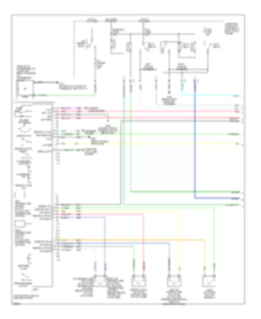
Manual A/C Wiring Diagram (1 of 2) for Chevrolet Impala LTZ 2007
List of elements for Manual A/C Wiring Diagram (1 of 2) for Chevrolet Impala LTZ 2007:
- (part of a/c compressor, on lower left front of engine) a/c compressor clutch
- A/c cmprsr fuse 10a
- A/c cmprsr relay
- A/c request ind
- A/c request switch
- Air temp a
- Air temp b
- Air temperature actuator (w/ auxiliary temperature control) (behind center of i/p on hvac case)
- Battery
- Blower motor sw
- Computer data lines system
- Defog rly ctrl
- Defogger
- Defogger system
- Emission 2 fuse 15a
- Fan 1 fuse 30a
- Fan 1 relay
- Fan 2 fuse 30a
- Fan 2 relay
- Fan 3 relay
- G100 (behind right headlamp, on frame)
- G113 (on front of automatic transaxle, left of g111)
- G201 (front of dash, above g202)
- G202 (on right side of steering column below c201)
- Gnd
- High
- Hot at all times
- Hot in run or start
- Hvac control module (center of dash)
- Ign 1 vol
- Illum
- Ind
- Interior lights system
- Left air temperature actuator (w/ auxiliary temperature control) (right of accelerator pedal)
- Left cooling fan diode
- Left temperature control switch (w/ auxiliary temperature control)
- Logic
- Low
- Low ref
- Mode actuator (on hvac assembly)
- Mode dr ctrl a
- Mode dr ctrl b
- Mode switch
- Off
- On ind
- Pnk
- Rear defogger switch
- Recirculation
- Recirculation a
- Recirculation actuator (on right side of hvac case)
- Recirculation b
- Recirculation switch
- Right air temperature actuator (w/ auxiliary temperature control) (behind center of dash, on hvac case)
- Right cooling fan diode
- Right temperature control switch (w/ auxiliary temperature control)
- Serial data
- Speed ctrl
- Tan
- Temp sens sig
- Underhood fuse block (mounted to right strut tower)
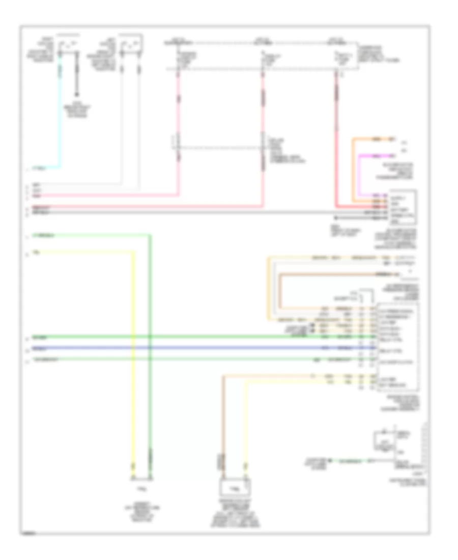
Manual A/C Wiring Diagram (2 of 2) for Chevrolet Impala LTZ 2007
List of elements for Manual A/C Wiring Diagram (2 of 2) for Chevrolet Impala LTZ 2007:
- (or 2751)
- 5.3l
- 5v reference 1
- A/c comp clutch
- A/c press signal
- A/c refrigerant pressure sensor (under air cleaner)
- Air bag/ display fuse 10a
- Ambient air temperature sensor (in front of radiator)
- Batt 4 fuse 30a
- Battery
- Blower motor (above foot area of passenger floor)
- Blower motor control processor (lower right side of hvac assembly, near blower motor)
- Computer data lines system
- D pnk
- Data bus +
- Data bus -
- Display fuse 10a
- Ect sens sig
- Engine control module (ecm) (inside air cleaner assembly)
- Engine coolant temperature (ect) sensor (5.3l: left front of engine at cylinder 1) (except 5.3l: left side of front cylinder head)
- Except 5.3l
- G100 (behind right headlamp, on frame)
- G200 (front of dash, left of g204)
- Gmlan serial data
- Gnd
- Hot at all times
- Hot coolant ind
- Hot in run or start
- Ign
- Instrument panel cluster (ipc)
- Left cooling fan (front of engine compt, mounted to left side of radiator)
- Logic
- Low ref
- Pnk
- Red
- Relay ctrl
- Right cooling fan (mounted to right side of radiator)
- Serial data
- Speed ctrl
- Splice pack sp206 (on i/p harness, near steering column)
- Tan
- Underhood fuse block (mounted to right strut tower)