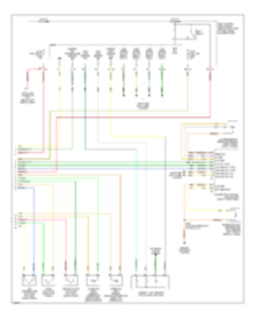
AIR CONDITIONING
Automatic A/C Wiring Diagram (1 of 2) for Chevrolet Malibu LS 2004

List of elements for Automatic A/C Wiring Diagram (1 of 2) for Chevrolet Malibu LS 2004:
- (behind grille, on left side of impact bar) ambient air temperature sensor
- (center console, front of body control module)
- (center console, front of body control module) g203
- A/c clu fuse 1 10a
- A/c clutch relay
- A/c compressor clutch
- A/c request ind
- A/c request switch
- A10
- A11
- A11 c2
- A12
- A2 c1
- A3 c1
- B1 c1
- B10
- B10 c2
- B11
- B12
- B9 c3
- Bat
- Batt
- Blower motor (below right side of dash)
- Blower motor control module (right side of dash, rear of hvac case)
- Blower motor switch
- Blr mtr spd ctrl
- Blr spd req sig
- C/fan 1 fuse 17 30a
- C/fan 2 fuse 18 30a
- C1 e3
- C2 a5
- C2 c4
- C3 b8
- Computer data lines system
- Cool fan 1 relay
- Cool fan 2 relay
- Cool ser/par relay
- Dr ctrl a
- Dr ctrl b
- E1 c2
- E8 c1
- Fresh air ind
- G106 (on trans, near pnp switch)
- G201
- Grd
- Hot at all times
- Hot in run or start
- Hvac control module (center of dash)
- Ign 3
- Inside air temperature sensor
- Interior lights system
- Left cooling fan
- Lmp sply voltage
- Logic
- Low ref
- Low spd gmlan
- Mode switch
- Recirculation actuator
- Recirculation ind
- Right cooling fan
- Sply voltage
- Tan
- Temp sens sig
- Temperature control
- Underhood fuse block (left side of engine compt)
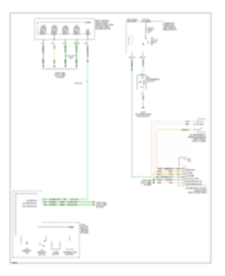
Automatic A/C Wiring Diagram (2 of 2) for Chevrolet Malibu LS 2004
List of elements for Automatic A/C Wiring Diagram (2 of 2) for Chevrolet Malibu LS 2004:
- 5v ref
- A/c refrigerant pressure sensor (right front strut tower)
- Air temperature actuator (top left side of dash)
- Ambient air temperature sensor sig
- Ambient light sensor (top of dash trim pad)
- Ambient light sensor low ref
- Body control module (bcm) (below right side of dash, near blower motor)
- C4 b6
- C4 e2
- Clu rly ctrl
- Computer data lines system
- Data link connector (dlc) (below left side of dash)
- Ect sens sig
- Engine controls system
- Engine coolant temperature (ect) sensor (left side of rear cyl head)
- Exterior lights system
- Grd
- High spd gm lan
- High spd rly ctrl
- High speed gm lan serial data +
- High speed gm lan serial data -
- Hot at all times
- Hvac ctrl (batt) fuse 10a
- Hvac ctrl (ign) fuse 10a
- Logic
- Low ref
- Low spd rly ctrl
- Low speed gm lan serial data
- Lower air temp sensor (under right side of dash, near console)
- Mode actuator (right kick panel)
- Powertrain control module (pcm) (front of battery)
- Recirculation actuator (top left side of dash)
- Run relay
- Run rly ctrl
- S106 (3 cm from breakout to fuel inj 3)
- Sens sig
- Sun load sensor sig
- Tan
- Upper air temp sensor (above accelerator pedal, on upper duct)
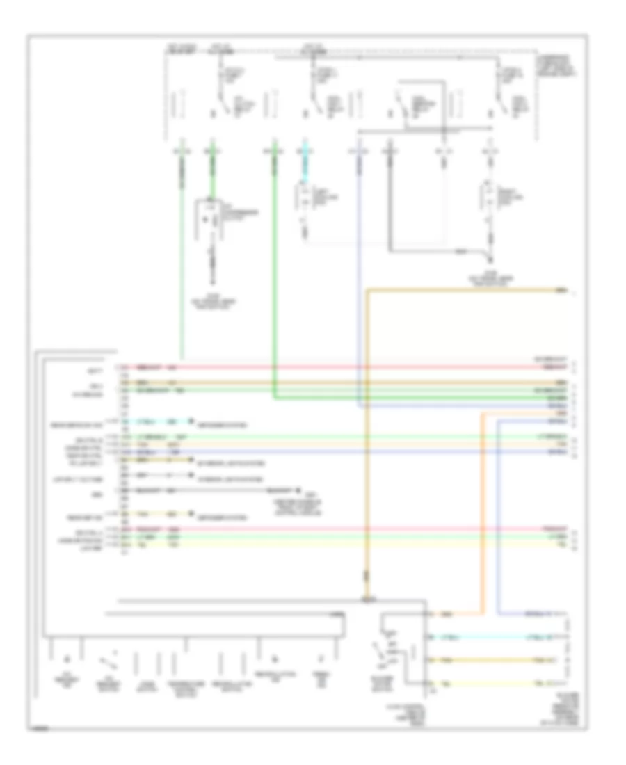
Compressor Wiring Diagram for Chevrolet Malibu LS 2004
List of elements for Compressor Wiring Diagram for Chevrolet Malibu LS 2004:
- (auto a/c)
- (man a/c)
- 2.2l 3.5l
- 5v ref
- A/c clu fuse 1 10a
- A/c clutch relay
- A/c compressor clutch
- A/c refrigerant pressure sensor (right front strut tower)
- A/c req sig
- A/c request ind
- A/c request switch
- Auto a/c
- Body control module (bcm) (below right side of dash, near blower motor)
- Clu rly ctrl
- Computer data lines system
- E1 c2
- E8 c1
- G106 (on trans, near pnp switch)
- High spd gm lan
- High speed gm lan serial data +
- High speed gm lan serial data -
- Hot at all times
- Hot in run or start
- Hvac control module (center of dash)
- Logic
- Low ref
- Low spd gmlan
- Low speed gm lan serial data
- Man a/c
- Mode switch
- Powertrain control module (pcm) (front of battery)
- Sens sig
- Tan
- Temperature control
- Underhood fuse block (left side of engine compt)
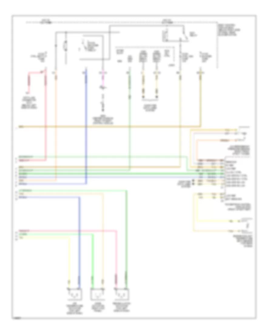
Manual A/C Wiring Diagram (1 of 2) for Chevrolet Malibu LS 2004
List of elements for Manual A/C Wiring Diagram (1 of 2) for Chevrolet Malibu LS 2004:
- (center console, front of body control module)
- A/c clu fuse 1 10a
- A/c clutch relay
- A/c compressor clutch
- A/c req sig
- A/c request ind
- A/c request switch
- A10
- A11
- A11 c2
- A12
- A2 c1
- A3 c1
- B1 c1
- B10
- B10 c2
- B11
- B12
- Batt
- Blower motor resistor assembly (on rear of hvac case)
- Blower motor switch
- C/fan 1 fuse 17 30a
- C/fan 2 fuse 18 30a
- C1 e3
- C2 g
- Cool fan 1 relay
- Cool fan 2 relay
- Cool ser/par relay
- Defogger system
- Dr ctrl a
- Dr ctrl b
- E1 c2
- E8 c1
- Exterior lights system
- Fresh air ind
- G106 (on trans, near pnp switch)
- G201
- Grd
- High
- Hot at all times
- Hot in run or start
- Hvac control module (center of dash)
- Ign 3
- Interior lights system
- Left cooling fan
- Lmp sply voltage
- Logic
- Low
- Low ref
- Mode dr ctrl
- Mode dr pos sig
- Mode switch
- Off
- Pk lmp sply
- Rear def ind
- Rear defog sw sig
- Recirculation ind
- Recirculation switch
- Right cooling fan
- Tan
- Temp dr ctrl
- Temperature control switch
- Underhood fuse block (left side of engine compt)
Manual A/C Wiring Diagram (2 of 2) for Chevrolet Malibu LS 2004
List of elements for Manual A/C Wiring Diagram (2 of 2) for Chevrolet Malibu LS 2004:
- 5v ref
- A/c refrigerant pressure sensor (right front strut tower)
- A/c req sig
- After blow
- Air temperature actuator (top left side of dash)
- Body control module (bcm) (below right side of dash, near blower motor)
- C4 b3
- Clu rly ctrl
- Computer data lines system
- D4 c4
- Data link connector (dlc) (below left side of dash)
- Ect sens sig
- Engine coolant temperature (ect) sensor (top rear of eng)
- G203 (center console, front of body control module)
- Grd
- High spd gm lan
- High spd rly ctrl
- High speed gm lan serial data +
- High speed gm lan serial data -
- Hot at all times
- Hvac blower fuse 20a
- Hvac blower high relay
- Hvac ctrl (batt) fuse 10a
- Hvac ctrl (ign) fuse 10a
- Logic
- Low ref
- Low spd rly ctrl
- Mode actuator (right kick panel)
- Powertrain control module (pcm) (front of battery)
- Recirculation actuator (top left side of dash)
- Run relay
- Run rly ctrl
- Sens sig
- Tan