AIR CONDITIONING
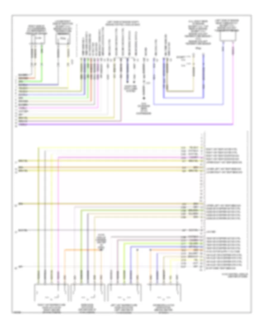
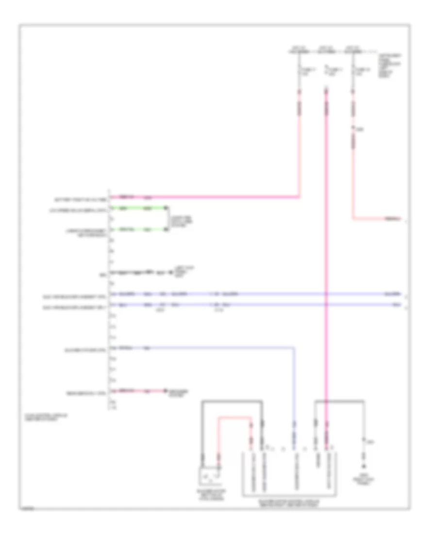
Automatic A/C Wiring Diagram (1 of 4) for Chevrolet Malibu LT 2013

List of elements for Automatic A/C Wiring Diagram (1 of 4) for Chevrolet Malibu LT 2013:
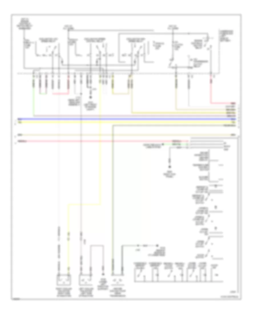
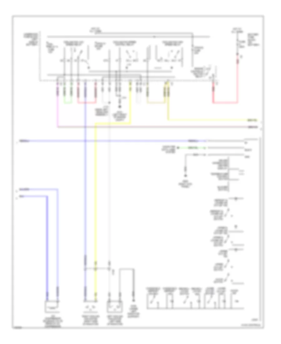
Automatic A/C Wiring Diagram (2 of 4) for Chevrolet Malibu LT 2013
List of elements for Automatic A/C Wiring Diagram (2 of 4) for Chevrolet Malibu LT 2013:
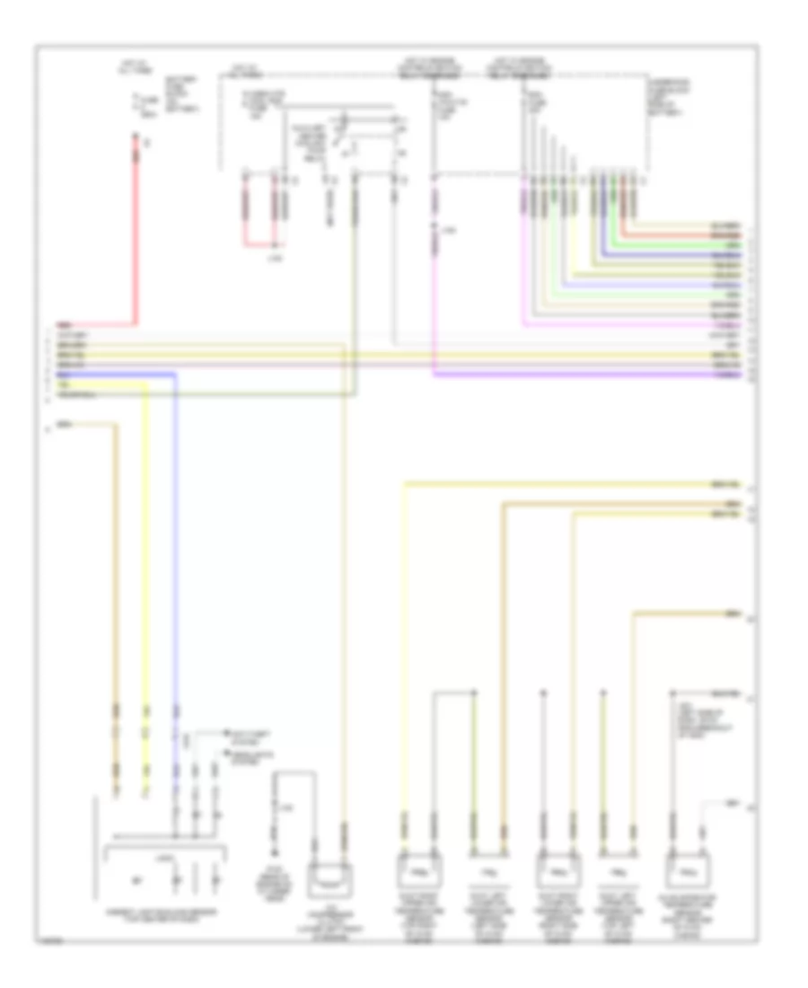
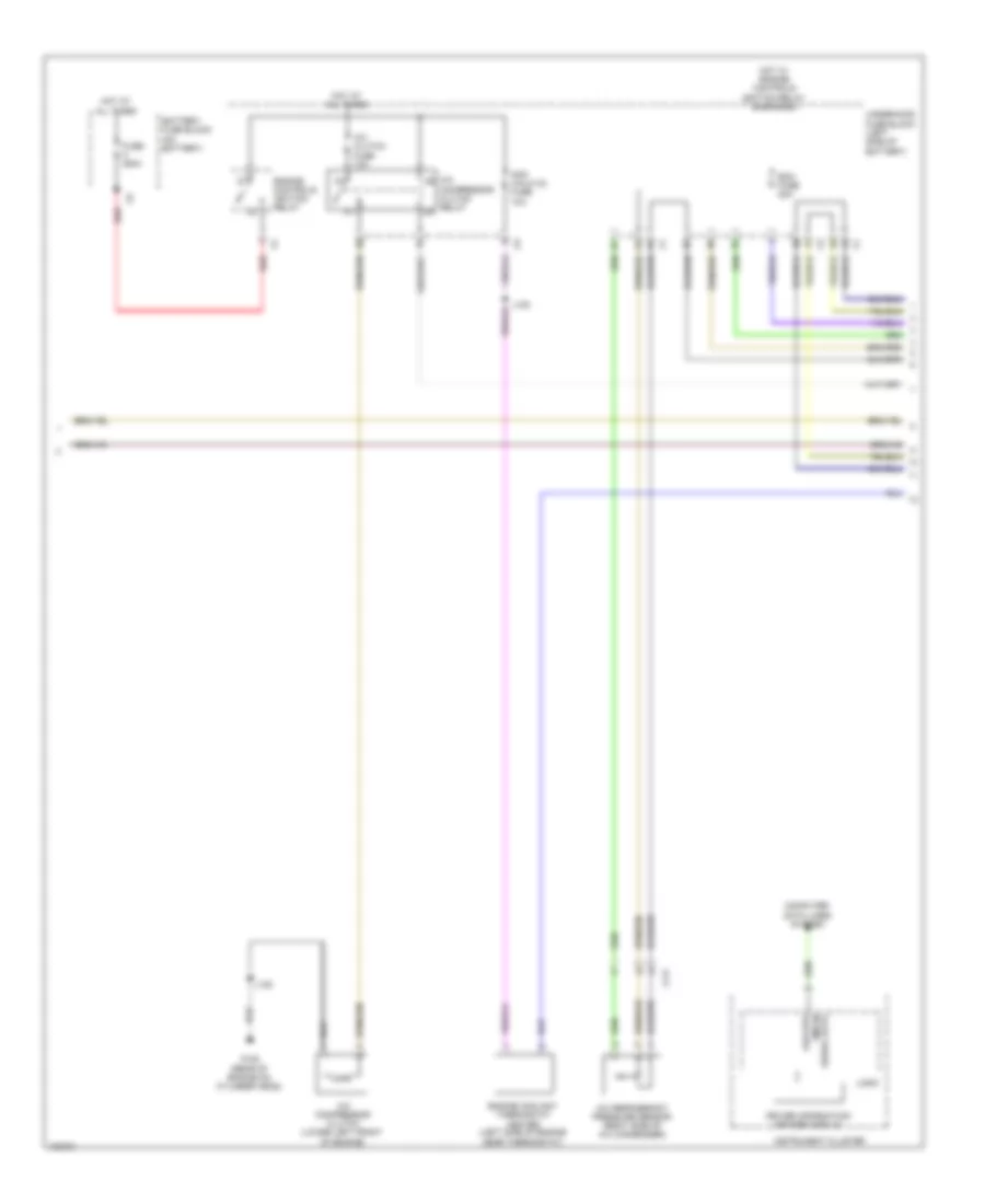
Automatic A/C Wiring Diagram (3 of 4) for Chevrolet Malibu LT 2013
List of elements for Automatic A/C Wiring Diagram (3 of 4) for Chevrolet Malibu LT 2013:
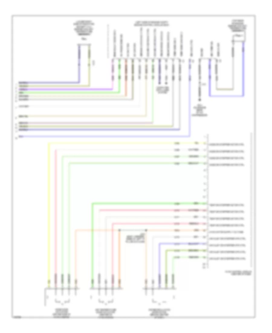
Automatic A/C Wiring Diagram (4 of 4) for Chevrolet Malibu LT 2013
List of elements for Automatic A/C Wiring Diagram (4 of 4) for Chevrolet Malibu LT 2013:
Manual A/C Wiring Diagram (1 of 4) for Chevrolet Malibu LT 2013
List of elements for Manual A/C Wiring Diagram (1 of 4) for Chevrolet Malibu LT 2013:
Manual A/C Wiring Diagram (2 of 4) for Chevrolet Malibu LT 2013
List of elements for Manual A/C Wiring Diagram (2 of 4) for Chevrolet Malibu LT 2013:
Manual A/C Wiring Diagram (3 of 4) for Chevrolet Malibu LT 2013
List of elements for Manual A/C Wiring Diagram (3 of 4) for Chevrolet Malibu LT 2013:
Manual A/C Wiring Diagram (4 of 4) for Chevrolet Malibu LT 2013
List of elements for Manual A/C Wiring Diagram (4 of 4) for Chevrolet Malibu LT 2013: