AIR CONDITIONING
Compressor Wiring Diagram for Chevrolet Metro LSi 1999

List of elements for Compressor Wiring Diagram for Chevrolet Metro LSi 1999:
- (i/p harness, 8 cm from blower motor breakout)
- A/c 1 relay
- A/c 2 relay
- A/c compressor clutch
- A/c compressor control module (below right side of dash, on evaporator case)
- A/c fuse 15a
- A/c off
- A/c refrigerant temperature switch (behind right side of dash)
- A/c relay
- A/c req
- A/c switch
- Blower speed selector switch
- Dual pres sw
- Dual pressure switch (right side of engine compartment, near strut tower)
- Evap temp
- Fuse box
- G103 (right front of engine compt)
- Heater fuse 20a
- Hot at all times
- Hot in on
- Junction block
- Off
- Pnk
- Powertrain control module (pcm) (behind right side of dash)
- Relay box
- S122 (main harn, at relay box)
- S134 (a/c jumper harn, right front of engine compartment)
- S233
- Sensor ground
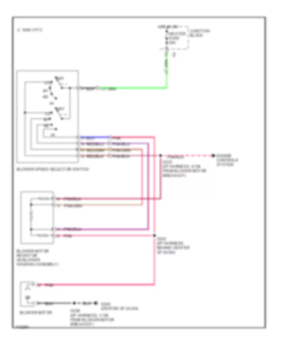
Heater Wiring Diagram for Chevrolet Metro LSi 1999
List of elements for Heater Wiring Diagram for Chevrolet Metro LSi 1999:
- 1995 vftc c
- Blower motor
- Blower motor resistor (in blower housing assembly)
- Blower speed selector switch
- Engine controls system
- G202 (center of dash)
- Heater fuse 20a
- Hot in on
- Junction block
- Off
- Pnk
- S232 (i/p harness, behind center of dash)
- S233 (i/p harness, 8 cm from blower motor breakout)
- S238 (i/p harness, 3 cm from blower motor breakout)
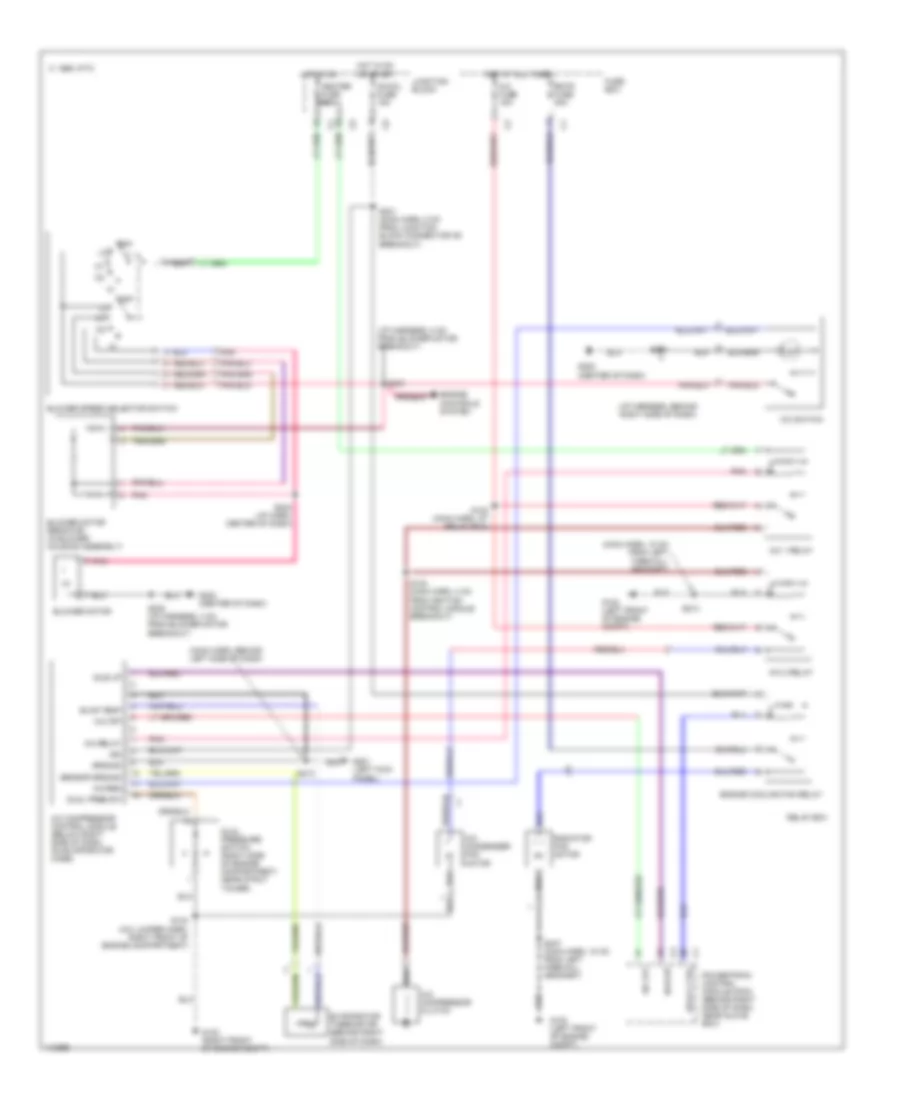
Manual A/C Wiring Diagram for Chevrolet Metro LSi 1999
List of elements for Manual A/C Wiring Diagram for Chevrolet Metro LSi 1999:
- (i/p harness, 8 cm from blower motor breakout)
- (i/p harness, behind right side of dash)
- (main harn, 18 cm from left firewall grommet)
- (main harn, behind left side of dash)
- 1995 vftc c
- A/c 1 relay
- A/c 2 relay
- A/c compressor clutch
- A/c compressor control module (below right side of dash, on evaporator case)
- A/c condenser fan motor
- A/c fuse 15a
- A/c off
- A/c relay
- A/c req
- A/c switch
- Blower motor
- Blower motor resistor (in blower housing assembly)
- Blower speed selector switch
- Dual pres sw
- Dual pressure switch (right side of engine compartment, near strut tower)
- Engine controls system
- Engine cooling fan relay
- Evap temp
- Evaporator thermistor (behind right side of dash)
- Fuse box
- G102 (left front of engine compt)
- G103 (right front of engine compt)
- G201 (left kick panel)
- G202 (center of dash)
- Ground
- Heater fuse 20a
- Hot at all times
- Hot in on
- Hot in on or start
- Idle up
- Idle-up
- Ig-coil fuse 15a
- Ign
- Junction block
- Off
- Pnk
- Powertrain control module (pcm) (behind right side of dash, near glove box)
- Radiator fan motor
- Rdtr fuse 30a
- Relay box
- Relay ctrl
- S122 (main harn, at relay box)
- S123 (main harn, 4 cm from ignition control module breakout)
- S134 (a/c jumper harn, right front of engine compartment)
- S210
- S213
- S231 (main harn, 8 cm from junction block connector c6 breakout)
- S232 (i/p harn, center of dash)
- S233
- S238 (i/p harness, 3 cm from blower motor breakout)
- S247 (main harn, 18 cm from left firewall grommet)
- S254
- Sensor ground