AIR CONDITIONING
Compressor Wiring Diagram for Chevrolet Monte Carlo Z34 1999

List of elements for Compressor Wiring Diagram for Chevrolet Monte Carlo Z34 1999:
- (engine harn, 10 cm from eng coolant level indicator module) (vin k) (engine harn, 4 cm from eng coolant fan motor 2 breakout) (vin m)
- (engine harn, 13 cm from eng cooling fan motor 1 breakout)
- A/c compressor clutch
- A/c compressor clutch diode
- A/c compressor clutch relay (in engine wiring harness junction block 1)
- A/c cont fuse 10a
- A/c request
- Engine wiring harness junction block 1
- Fuse 15a
- Fuse block
- G117 (lower left front of engine)
- Heater-a/c control
- Hot in run
- Hot in run, bulb test or start
- Ignition
- Nca
- Pnk
- Powertrain control module (pcm) (right side of engine compartment, forward of strut tower)
- Relay control
- S105
- S164
- S233 (i/p harn, 4 cm from i/p compt lamp breakout)
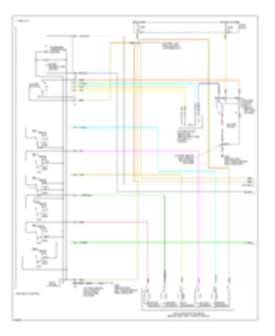
Manual A/C Wiring Diagram, Dual Zone A/C (1 of 2) for Chevrolet Monte Carlo Z34 1999
List of elements for Manual A/C Wiring Diagram, Dual Zone A/C (1 of 2) for Chevrolet Monte Carlo Z34 1999:
- (i/p harn, 4 cm from i/p compt lamp breakout)
- (i/p harn, behind right side of driver knee bolster)
- A/c solenoid
- B-lv
- Bi-level solenoid
- Blend
- Blower motor
- Blower motor relay (behind left side of dash)
- Blower motor resistors (behind right side of dash, in plenum)
- Blower switch
- C 1995 vftc
- Def
- Defrost solenoid
- Driver temperature control
- Fuse 15a
- Fuse 20a
- Fuse block
- G205 (behind dash, left side of brake pedal bracket)
- Heater solenoid
- Heater-a/c control
- Hot at al times
- Hot in run
- Htr
- Max
- Norm
- Off
- Passenger temperature control
- Recirc solenoid
- Red
- S213
- S233
- Solid state
- Tan
- Vacuum/electric solenoid (behind dash, right side of plenum)
- Vnt
- Vnt b-lv
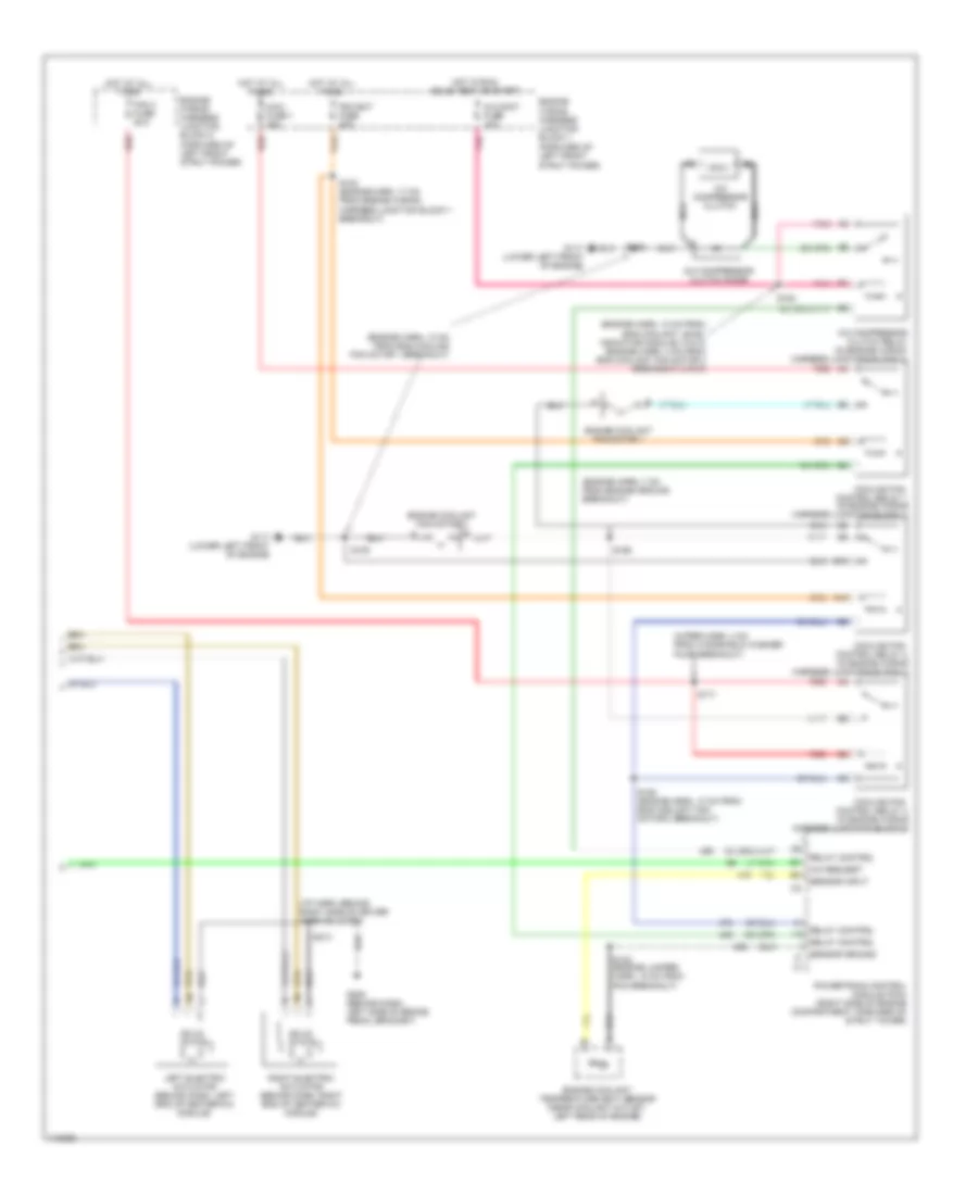
Manual A/C Wiring Diagram, Dual Zone A/C (2 of 2) for Chevrolet Monte Carlo Z34 1999
List of elements for Manual A/C Wiring Diagram, Dual Zone A/C (2 of 2) for Chevrolet Monte Carlo Z34 1999:
- (engine harn, 10 cm from eng coolant level indicator module) (vin k) (engine harn, 4 cm from eng coolant fan motor 2 breakout) (vin m)
- (engine harn, 13 cm from eng cooling fan motor 1 breakout)
- (engine harn, 7 cm from engine ground breakout)
- (forward of left front strut power)
- (i/p harn, behind right side of driver knee bolster)
- (wiper harn, 4 cm from windshield washer pump breakout)
- A/c compressor clutch
- A/c compressor clutch diode
- A/c compressor clutch relay (in engine wiring harness junction block 1)
- A/c cont fuse 10a
- A/c request
- B10
- C10
- Cooling fan control relay 1 (in engine wiring harness junction block 1)
- Cooling fan control relay 2 (in engine wiring harness junction block 1)
- Cooling fan control relay 3 (in engine wiring harness junction block 2)
- Engine coolant fan motor 1
- Engine coolant fan motor 2
- Engine coolant temperature (ect) sensor (near coolant outlet, left rear of engine)
- Engine wiring harness junction block 1
- Engine wiring harness junction block 2 (forward of left front strut power)
- Fan 3 fuse 25a
- G117 (lower left front of engine)
- G205 (behind dash, left side of brake pedal bracket)
- Hot at all times
- Hot in run, bulb test or start
- Left electric actuator (behind dash, left end of heater-a/c module)
- Maxi fuse 1 30a
- Nca
- Pcm bat fuse 20a
- Pnk
- Powertrain control module (pcm) (right side of engine compartment, forward of strut tower)
- Red
- Relay control
- Right electric actuator (behind dash, right end of heater-a/c module)
- S102 (engine harn, 17 cm from engine wiring harness junction block 1 breakout)
- S105
- S122 (engine jumper harn, 15 cm from pcm breakout)
- S163 (engine harn, 10 cm from eng coolant fan motor 2 breakout)
- S164
- S165
- S171
- S213
- Sensor ground
- Sensor input
- Solid state
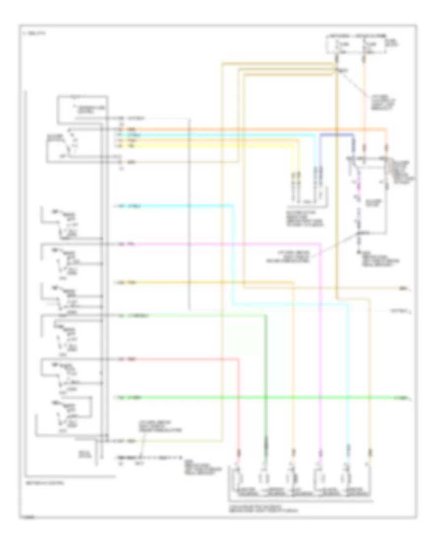
Manual A/C Wiring Diagram, Standard (1 of 2) for Chevrolet Monte Carlo Z34 1999
List of elements for Manual A/C Wiring Diagram, Standard (1 of 2) for Chevrolet Monte Carlo Z34 1999:
- (i/p harn, 4 cm from i/p compt lamp breakout)
- (i/p harn, behind right side of driver knee bolster)
- A/c solenoid
- B-lv
- Bi-level solenoid
- Blend
- Blower motor
- Blower motor relay (behind right side of dash)
- Blower motor resistors (behind right side of dash, in plenum)
- Blower switch
- C 1995 vftc
- Def
- Defrost solenoid
- Fuse 15a
- Fuse 20a
- Fuse block
- G205 (behind dash, left side of brake pedal bracket)
- Heater solenoid
- Heater-a/c control
- Hot at al times
- Hot in run
- Htr
- Max
- Norm
- Off
- Recirc solenoid
- Red
- S213
- S233
- Solid state
- Tan
- Temperature control
- Vacuum/electric solenoid (behind dash, right side of plenum)
- Vnt
- Vnt b-lv
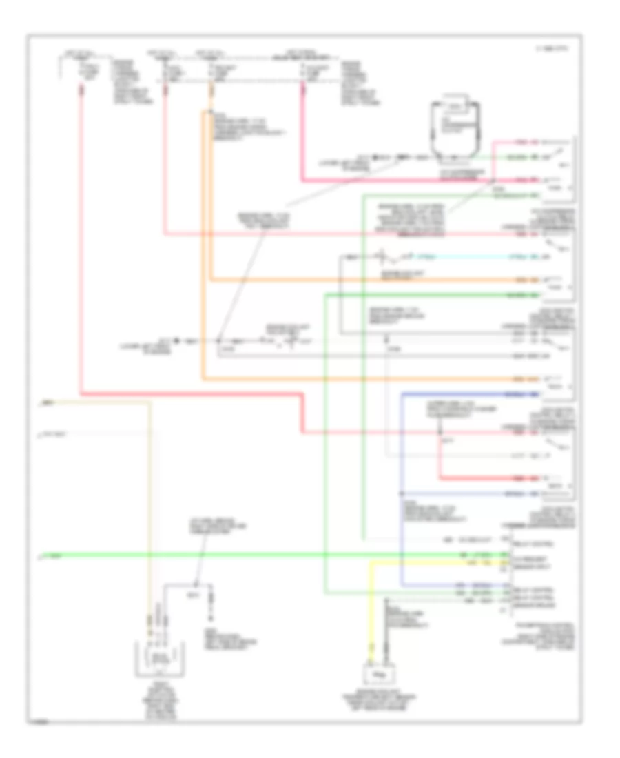
Manual A/C Wiring Diagram, Standard (2 of 2) for Chevrolet Monte Carlo Z34 1999
List of elements for Manual A/C Wiring Diagram, Standard (2 of 2) for Chevrolet Monte Carlo Z34 1999:
- (engine harn, 10 cm from eng coolant level indicator module) (vin k) (engine harn, 4 cm from eng coolant fan motor 2 breakout) (vin m)
- (engine harn, 13 cm from eng coolant fan 1 breakout)
- (engine harn, 7 cm from engine ground breakout)
- (i/p harn, behind right side of driver knee bolster)
- (wiper harn, 4 cm from windshield washer pump breakout)
- A/c compressor clutch
- A/c compressor clutch diode
- A/c compressor clutch relay (in engine wiring harness junction block 1)
- A/c cont fuse 10a
- A/c request
- B10
- C 1995 vftc
- C10
- Cooling fan control relay 2 (in engine wiring harness junction block 1)
- Cooling fan control relay 3 (in engine wiring harness junction block 2)
- Coolong fan control relay 1 (in engine wiring harness junction block 1)
- Engine coolant fan motor 1
- Engine coolant fan motor 2
- Engine coolant temperature (ect) sensor (near coolant outlet, left rear of engine)
- Engine wiring harness junction block 1 (forward of right front strut tower)
- Fan 3 fuse 25a
- G117 (lower left front of engine)
- G205 (behind dash, left side of brake pedal bracket)
- Hot at all times
- Hot in run, bulb test or start
- Maxi fuse 1 30a
- Nca
- Pcm bat fuse 20a
- Pnk
- Powertrain control module (pcm) (right side of engine compartment, forward of strut tower)
- Red
- Relay control
- Right electric actuator (behind dash, right end of heater- a/c module)
- S102 (engine harn, 17 cm from engine wiring harness junction block 1 breakout)
- S105
- S122 (engine harn, 15 cm from pcm breakout)
- S163 (engine harn, 10 cm from eng coolant fan motor 2 breakout)
- S164
- S165
- S171
- S213
- Sensor ground
- Sensor input
- Solid state