AIR CONDITIONING
Compressor Wiring Diagram for Chevrolet Venture 2004

List of elements for Compressor Wiring Diagram for Chevrolet Venture 2004:
- (in engine compt, left and above starter) g117
- +5v reference
- 5 volts
- A/c clu diode
- A/c clu fuse 10a
- A/c clu relay
- A/c compressor clutch
- A/c press signal
- A/c refrigerant pressure sensor (left side of engine compt, below accumulator)
- A/c request
- C11
- Comp control
- Drl/hvac/ temp/htd st fuse 10a
- Engine controls system
- Evaporative temperature sensor (behind center of dash, on hvac assy)
- G200 (right side of dash)
- Ground
- Hot in run
- Hot in run, bulb test or start
- Hvac control module
- I/p fuse block (right side of dash)
- Ignition
- Low ref
- Low reference
- Powertrain control module (left front side of engine compt, in air cleaner assembly)
- S105 (engine harn, near breakout for engine coolant fan 1)
- S167 (engine harn, near breakout for pcm)
- S213 (dash harn, near breakout for cigar lighter)
- Underhood fuse block (right front of engine compt)
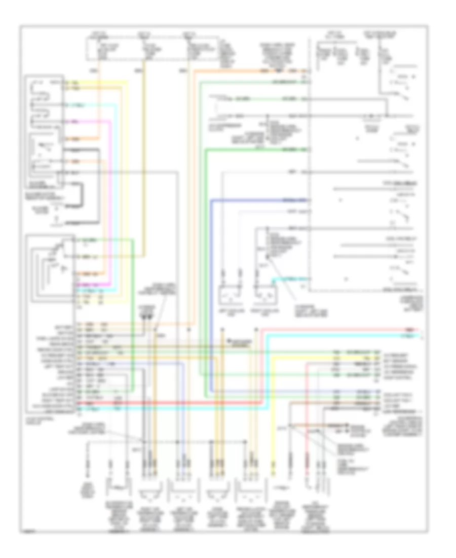
Manual A/C Wiring Diagram, with Video Entertainment (1 of 2) for Chevrolet Venture 2004
List of elements for Manual A/C Wiring Diagram, with Video Entertainment (1 of 2) for Chevrolet Venture 2004:
- (dash harn, near breakout for cigar lighter)
- (dash harn, near breakout for relay center)
- (dash harn, near breakout for window wiper/ washer and multifunction switch) s202
- (engine harn, near breakout. for pcm)
- (fuel inj harn, near breakout for c102)
- (in engine compt, left and above starter)
- +5v
- +5v reference
- A/c clu diode
- A/c clu fuse 10a
- A/c clu relay
- A/c compressor clutch
- A/c press signal
- A/c refrigerant pressure sensor (left side
- A/c request
- A/c request sig
- A10
- Aux mode door ctrl
- Battery
- Blower motor
- Blower motor relay
- Blower motor resistor assembly
- Blower sw off
- C10
- C11
- Comp control
- Cool fan 1 fuse 30a
- Cool fan 2 fuse 30a
- Cool fan 1 relay
- Cool fan 2 relay
- Cool fan relay
- Coolant fan 1
- Coolant fan 2
- Defogger system
- Drl/hvac/ temp/htd st fuse 10a
- Ect sensor
- Engine controls system
- Engine coolant temperature (ect) sensor (top left rear of engine)
- Evaporative temperature sensor (behind center of dash, on hvac assembly)
- F11
- Frt hvac hi blwr c.b. 30a
- G117
- G200 (right side of dash)
- Ground
- Hot at all times
- Hot in run
- Hot in run, bulb test or start
- Hvac blower fuse 25a
- Hvac control module
- I/p fuse block (behind right side of dash)
- Ignition
- Interior lights system
- Lamp dim sig
- Left air temperature actuator (left side of hvac assembly)
- Left cooling fan
- Left temp act
- Low ref
- Low reference
- Mode actuator (left side of hvac assembly)
- Mode door ctrl
- Nca
- Of engine compt, below accumulator)
- Off
- Park lamps on sig
- Powertrain control module (left front side of engine compt, in air cleaner assembly)
- Radio fuse 10a
- Rear defog
- Recirc door ctrl
- Recirculation actuator (behind right side of dash, above blower motor)
- Red
- Right air temperature actuator (right side of hvac assembly)
- Right cooling fan
- Right temp act
- S105 (engine harn, near breakout for engine coolant fan 1)
- S110
- S167
- S213
- S264
- Tan
- Underhood fuse block (above battery)
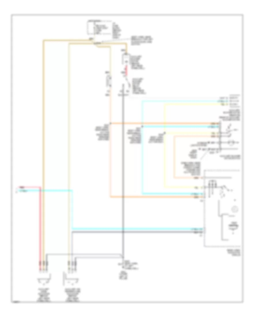
Manual A/C Wiring Diagram, with Video Entertainment (2 of 2) for Chevrolet Venture 2004
List of elements for Manual A/C Wiring Diagram, with Video Entertainment (2 of 2) for Chevrolet Venture 2004:
- (body harn, near breakout for left sliding door jamb switch)
- (dash harn, near breakout for window wiper/ washer and multifunction switch)
- At left wheelwell)
- Auxiliary air temperature actuator (behind left rear wheelwell)
- Auxiliary blower motor (behind left rear wheelwell)
- Auxiliary blower motor relay (behind left rear wheelwell)
- Auxiliary blower motor resistor (rear of auxiliary blower motor)
- Auxiliary blower motor switch
- Auxiliary mode actuator (behind left rear wheelwell)
- G200 (right side of dash)
- G401 (lower
- Hot in run
- I/p fuse block (behind right side of dash)
- Interior lights system
- Left "d" pillar)
- Rear video/ audio/hvac module
- Red
- Rr hvac/ temp cont fuse 25a
- S230
- S339 (body harn, near break- out for g301)
- S341 (body harn, near break- out for radio rear speaker amplifier)
- S343 (body harn, near break- out for radio rear speaker amplifier)
- S345
- Temp control
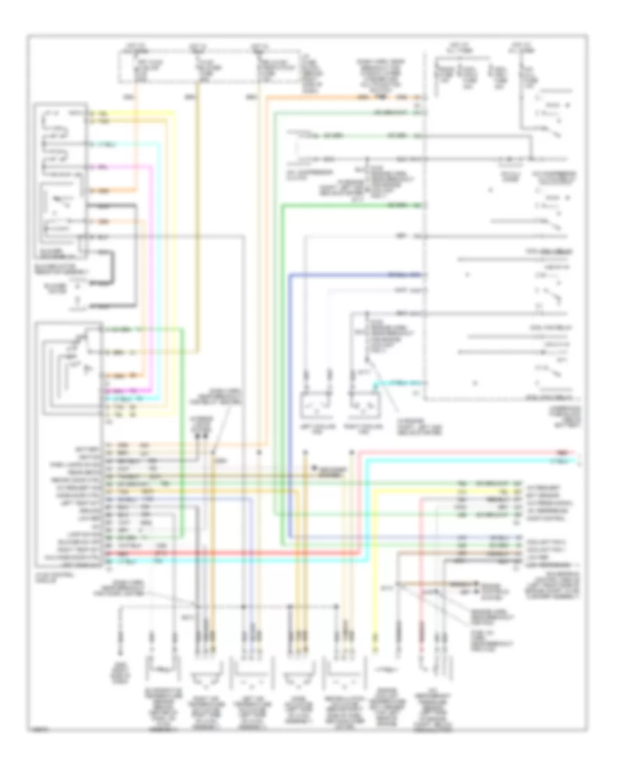
Manual A/C Wiring Diagram, without Video Entertainment (1 of 2) for Chevrolet Venture 2004
List of elements for Manual A/C Wiring Diagram, without Video Entertainment (1 of 2) for Chevrolet Venture 2004:
- (dash harn, near breakout for cigar lighter)
- (dash harn, near breakout for relay center)
- (dash harn, near breakout for window wiper/ washer and multifunction switch) s202
- (engine harn, near breakout. for pcm)
- (fuel inj harn, near breakout for c102)
- (in engine compt, left and above starter)
- +5v
- +5v reference
- A/c compressor clutch
- A/c clu diode
- A/c clu fuse 10a
- A/c compressor clutch relay
- A/c press signal
- A/c refrigerant pressure sensor (left side
- A/c request
- A/c request sig
- A10
- Aux mode door ctrl
- Battery
- Blower motor
- Blower motor relay
- Blower motor resistor assembly
- Blower sw off
- C10
- C11
- Comp control
- Cool fan 1 fuse 30a
- Cool fan 2 fuse 30a
- Cool fan 1 relay
- Cool fan 2 relay
- Cool fan relay
- Coolant fan 1
- Coolant fan 2
- Defogger system
- Drl/hvac/ temp/htd st fuse 10a
- Ect sensor
- Engine controls system
- Engine coolant temperature (ect) sensor (top left rear of engine)
- Evaporative temperature sensor (behind center of dash, on hvac assembly)
- F11
- Frt hvac hi blwr c.b. 30a
- G117
- G200 (right side of dash)
- Ground
- Hot at all times
- Hot in run
- Hvac blower fuse 25a
- Hvac control module
- I/p fuse block (behind right side of dash)
- Ignition
- Interior lights system
- Lamp dim sig
- Left air temperature actuator (left side of hvac assembly)
- Left cooling fan
- Left temp act
- Low ref
- Low reference
- Mode actuator (left side of hvac assembly)
- Mode door ctrl
- Nca
- Of engine compt, below accumulator)
- Off
- Park lamps on sig
- Powertrain control module (left front side of engine compt, in air cleaner assembly)
- Radio fuse 10a
- Rear defog
- Recirc door ctrl
- Recirculation actuator (behind right side of dash, above blower motor)
- Red
- Right air temperature actuator (right side of hvac assembly)
- Right cooling fan
- Right temp act
- S105 (engine harn, near breakout for engine coolant fan 1)
- S110
- S167
- S213
- S264
- Tan
- Underhood fuse block (above battery)
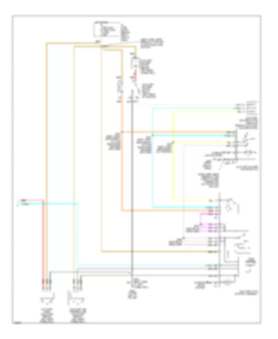
Manual A/C Wiring Diagram, without Video Entertainment (2 of 2) for Chevrolet Venture 2004
List of elements for Manual A/C Wiring Diagram, without Video Entertainment (2 of 2) for Chevrolet Venture 2004:
- (body harn, near breakout for left sliding door jamb switch)
- (dash harn, near breakout for window wiper/ washer and multifunction switch)
- At left wheelwell)
- Auxiliary air temperature actuator (behind left rear wheelwell)
- Auxiliary blower motor (behind left rear wheelwell)
- Auxiliary blower motor relay (left rear of vehicle)
- Auxiliary blower motor resistor (rear of auxiliary blower motor)
- Auxiliary blower motor switch
- Auxiliary hvac control assembly
- Auxiliary mode actuator (behind left rear wheelwell)
- G200 (right side of dash)
- G401 (lower
- Hot in run
- I/p fuse block (behind right side of dash)
- Interior lights system
- Left "d" pillar)
- Red
- Rr hvac/ temp cont fuse 25a
- S230
- S339 (body harn, near break- out for g301)
- S341 (body harn, near break- out for radio rear speaker amplifier)
- S343 (body harn, near break- out for radio rear speaker amplifier)
- S345
- S394 (center of headliner)
- S396 (center of headliner)
- Temp control