AIR CONDITIONING
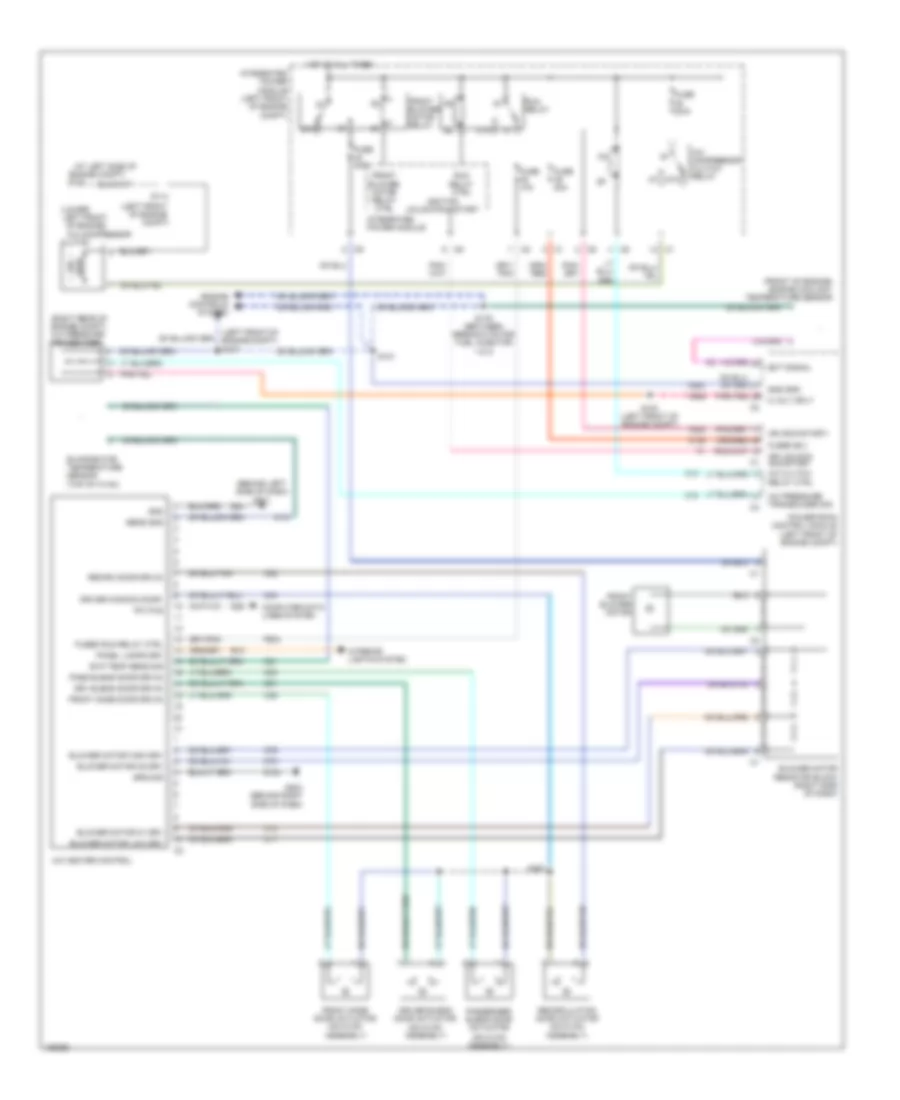
Automatic A/C Wiring Diagram for Chrysler Pacifica Touring 2005

List of elements for Automatic A/C Wiring Diagram for Chrysler Pacifica Touring 2005:
Manual A/C Wiring Diagram for Chrysler Pacifica Touring 2005
List of elements for Manual A/C Wiring Diagram for Chrysler Pacifica Touring 2005: